Toyota Sienna Service Manual: Reassembly
1. INSTALL OIL PUMP COVER
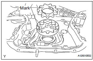
(a) Coat the drive and driven rotors with engine oil and place them into the timing chain cover with the marks facing outward (oil pump cover side). Check that the rotors rotate smoothly.
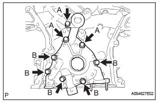
(b) Install the oil pump cover with the 8 bolts.
Torque: 9.1 N*m (93 kgf*cm, 81 in.*lbf)
Bolt length 
2. INSTALL OIL PUMP RELIEF VALVE
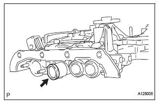
(a) Coat the oil pump relief valve with engine oil.
(b) Insert the relief valve and relief valve spring into the oil pump cover hole.
(c) Using a 27 mm socket wrench, install the plug.
Torque: 49 N*m (500 kgf*cm, 37 ft.*lbf)
 Inspection
1. INSPECT OIL PUMP RELIEF VALVE
(a) Coat the relief valve with engine oil and check that it
falls smoothly into the valve hole under its own
weight.
If the valve does not fall smoothly, rep ...
 Installation
1. INSTALL TIMING CHAIN CASE OIL SEAL
(a) Using SST, tap in a new oil seal until its surface is
flush with the timing chain case edge.
SST 09223-22010, 09506-35010
NOTICE:
Keep the ...
Other materials:
Checking and replacing
fuses
If any of the electrical components do not operate, a fuse may
have blown. If this happens, check and replace the fuses as necessary.
Turn the engine switch to the “LOCK” position (vehicles without a
smart key system) or off (vehicles with a smart key system).
Open the fuse box cover.
...
Mirror Motor Circuit
DESCRIPTION
A mirror control switch signal and memorized mirror positions are sent to the
outer mirror control ECU.
The outer mirror control ECU drives the selected mirror UP, DOWN, LEFT and RIGHT
in response to the
inputs.
HINT:
The power mirror control system is part of the large-scale ...
Safety information
for children
Observe the following precautions when children are in the vehicle.
Use a child restraint system appropriate for the child, until the
child becomes large enough to properly wear the vehicle’s seat
belt.
It is recommended that children sit in the rear seats to avoid
accidental
contact ...
