Toyota Sienna Service Manual: Slip Indicator Light Remains ON
DESCRIPTION
The skid control ECU is connected to the combination meter via CAN and multiplex communications.
The SLIP indicator blinks during VSC and/or TRAC operation.
When the system fails, the SLIP indicator comes on to warn the driver.
WIRING DIAGRAM
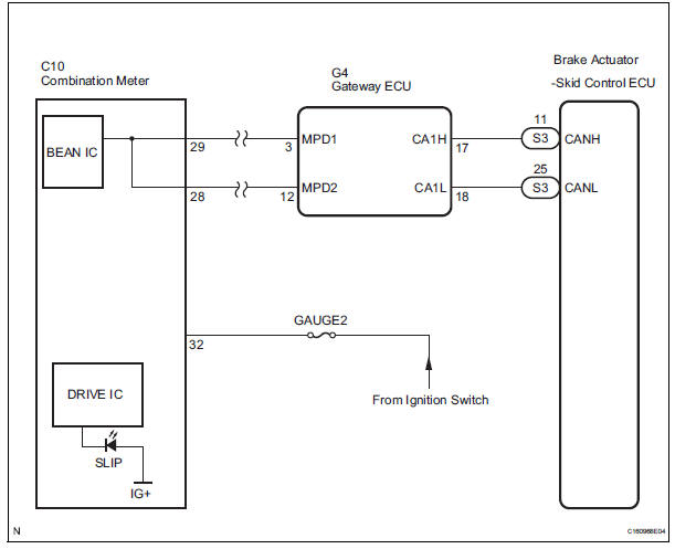
INSPECTION PROCEDURE
NOTICE: When replacing the brake actuator assembly, perform zero point calibration (See page BC-70).
1 CHECK CAN COMMUNICATION SYSTEM
(a) Check if the CAN communication system DTC is output (See page CA-17).
Result 

2 CHECK MULTIPLEX COMMUNICATION SYSTEM
(a) Check if the multiplex communication system DTC is output (See page MP-14).
Result 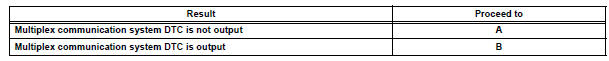

3 CHECK IF SKID CONTROL ECU CONNECTOR IS SECURELY CONNECTED
(a) Check if the skid control ECU connector is securely connected.
OK: The connector is securely connected.

4 CHECK BATTERY
(a) Check the battery voltage.
Standard voltage: 11 to 14 V

5 INSPECT COMBINATION METER ASSEMBLY
(a) Perform Active Test of the combination meter (meter CPU) using the intelligent tester (See page ME-19).
OK: The SLIP indicator light turns on or off in accordance with the intelligent tester.
HINT: If troubleshooting has been carried out according to the Problem Symptoms Table, refer back to the table and proceed to the next step before replacing the part (See page BC-79).

REPLACE BRAKE ACTUATOR ASSEMBLY
 TRAC OFF Indicator Light does not Come ON
DESCRIPTION
The skid control ECU is connected to the combination meter via CAN and
multiplex communications.
When the traction OFF switch is turned on, the TRAC OFF indicator light will
come o ...
 Slip Indicator Light does not Come ON
DESCRIPTION
The skid control ECU is connected to the combination meter via CAN and
multiplex communications.
The SLIP indicator blinks during VSC and/or TRAC operation.
When the system fails, ...
Other materials:
Refrigerant
On-vehicle inspection
1. INSPECT REFRIGERANT PRESSURE WITH MANIFOLD GAUGE SET
(a) This method uses a manifold gauge set to locate
problem areas. Read the manifold gauge pressure
when these conditions are established.
Test conditions:
Temperature at the air inlet is 30 to 35°C (86 to
95 ...
DTC check / clear
1. CHECK DTC (USING INTELLIGENT TESTER)
Checking DTCs.
Connect the intelligent tester to the DLC3.
Turn the ignition switch ON.
Read DTCs by following the prompts on the
tester screen.
HINT:
Refer to the intelligent tester operator's manual
for further details.
2. CLEAR DTC ...
Installation
1. INSTALL CRANKSHAFT POSITION SENSOR
Apply a light coat of engine oil to the O-ring on the
crankshaft position sensor.
Install the crankshaft position sensor with the bolt.
Torque: 9.0 N*m (92 kgf*cm, 80 in.*lbf)
Connect the crankshaft position sensor connector.
...
