Toyota Sienna Service Manual: Disassembly
1. REMOVE MAGNETIC CLUTCH ASSEMBLY
(a) Place the compressor and magnetic clutch in a vise.
(b) Using locking pliers, hold the magnetic clutch hub.
(c) Remove the bolt, magnetic clutch hub, and magnetic clutch washers.
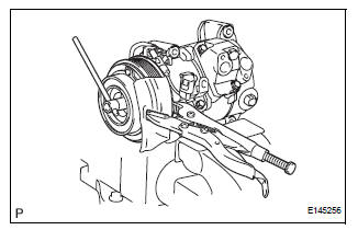
HINT: There is no set number of magnetic clutch washers because they are used for adjustment.
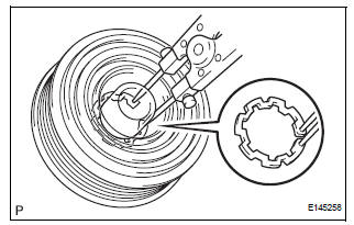
(d) Using a snap ring expander, remove the snap ring and magnetic clutch rotor.
NOTICE: Take care not to damage the seal cover of the bearing when removing the snap ring.
(e) Remove the screw and disconnect the connector.
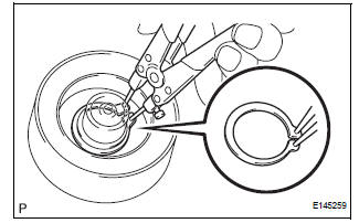
(f) Using a snap ring expander, remove the snap ring and magnetic clutch stator.
 Removal
1. RECOVER REFRIGERANT FROM REFRIGERATION
SYSTEM (See page AC-172)
2. REMOVE FRONT WHEEL RH
3. REMOVE FRONT FENDER APRON SEAL RH (See
page EM-26)
4. REMOVE V-RIBBED BELT (See page EM-6)
5. REMOV ...
 Inspection
1. INSPECT MAGNETIC CLUTCH CLEARANCE
(a) Set the dial indicator to the magnetic clutch hub.
(b) Connect the battery positive lead to the terminal 1 of
the magnet clutch connector and the nega ...
Other materials:
Unlock Warning Switch Circuit
DESCRIPTION
The unlock warning switch detects if the key is in the ignition key cylinder.
The unlock warning switch turns on when the key is inserted into the ignition
key cylinder and turns off
when the key is removed from the cylinder.
The body ECU is connected to the unlock warning swit ...
Checking and replacing
fuses
If any of the electrical components do not operate, a fuse may
have blown. If this happens, check and replace the fuses as necessary.
Turn the engine switch to the “LOCK” position (vehicles without a
smart key system) or off (vehicles with a smart key system).
Open the fuse box cover.
...
Rear Air Outlet Damper Control Servo Motor Circuit
DESCRIPTION
This circuit turns the servo motor and changes each damper position by
receiving the signals from the A/
C amplifier.
The rear air outlet damper servo motor switches the air outlet mode by rotating
(normal, reverse) with
electrical power from the A/C amplifier.
WIRING DIAGRAM
...
