Toyota Sienna Service Manual: Rear Clearance Sonar Sensor RH Circuit
DESCRIPTION
An ultrasonic sensor consists of a sensor portion that transmits and receives ultrasonic waves and a preamplifier that amplifies them. The ultrasonic sensor outputs the ultrasonic waves and sends the received signals to the clearance warning ECU.
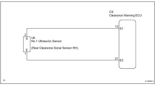
WIRING DIAGRAM
INSPECTION PROCEDURE
1 INSPECT NO. 1 ULTRASONIC SENSOR
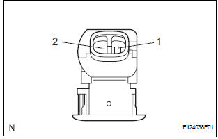
- Remove the No. 1 ultrasonic sensor.
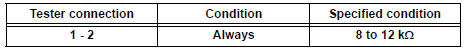
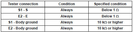
- Measure the resistance according to the value(s) in the table below.
Standard resistance
2 CHECK HARNESS AND CONNECTOR (CLEARANCE WARNING ECU - NO. 1 ULTRASONIC SENSOR)
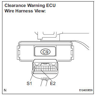
- Disconnect the C9 connector from the clearance warning ECU.
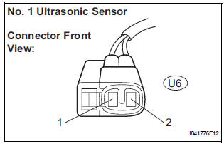
- Disconnect the U6 connector from the No. 1 ultrasonic sensor.
- Measure the resistance according to the value(s) in the table below.
Standard resistance
PROCEED TO NEXT CIRCUIT INSPECTION SHOWN IN PROBLEM SYMPTOMS TABLE
 Rear Clearance Sonar Sensor LH Circuit
DESCRIPTION
An ultrasonic sensor consists of a sensor portion that transmits and receives
ultrasonic waves and a preamplifier
that amplifies them. The ultrasonic sensor outputs the ultrasonic wave ...
 No. 1 Clearance Warning Buzzer Circuit
DESCRIPTION
The clearance warning ECU receives the ultrasonic sensor signal to sound the
front warning buzzer.
WIRING DIAGRAM
INSPECTION PROCEDURE
1 INSPECT FRONT BUZZER
Remove the c ...
Other materials:
System description
1. BRIEF DESCRIPTION
The CAN (Controller Area Network) is a serial data
communication system for real time application. It is
a vehicle multiplex communication system which
has a high communication speed (500 kbps) and
the ability to detect malfunctions.
By pairing the CANH and CANL bu ...
Vehicle Position Mark is not Updated
INSPECTION PROCEDURE
1 CHECK MAP DISC
Check that the map disc is not deformed or cracked.
OK:
No deformations or cracks on map disc.
2 CHECK MAP DISPLAY
Check if a touch scroll can be performed on the map
display.
OK:
Touch scroll can be performed
3 CHECK VEHICLE SENSOR (NAV ...
Problem symptoms table
HINT:
Use the table below to help determine the cause of the
problem symptoms. The potential causes of the symptoms
are listed in order of probability in the ''Suspected Area''
column of the table. Check each symptom by checking the
suspected areas in the order they are listed. Rep ...
