Toyota Sienna Service Manual: Coolant Thermostat (Coolant Temperature Below Thermostat Regulating Temperature)
DTC P0128 Coolant Thermostat (Coolant Temperature Below Thermostat Regulating Temperature)
HINT: This DTC relates to the thermostat.
DESCRIPTION This DTC is set when the Engine Coolant Temperature (ECT) does not reach 75C (167F) despite sufficient engine warm-up time
|
DTC No. |
DTC Detection Condition |
Trouble Area |
|
P0128 |
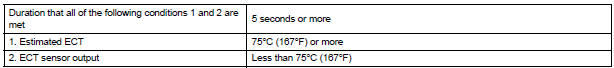
Conditions (a), (b) and (c) are met for 5 seconds (2 trip
detection logic):
|
|
MONITOR DESCRIPTION
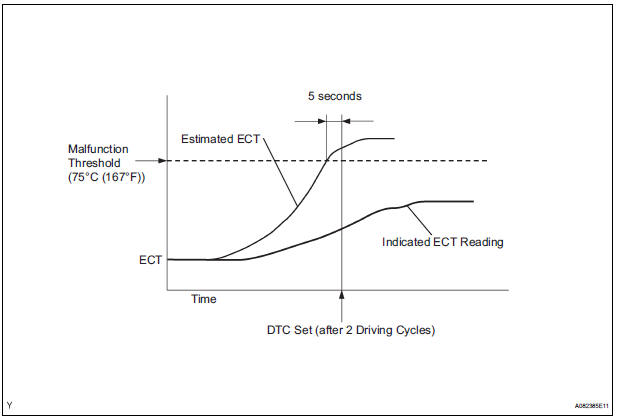
The ECM estimates the ECT based on the starting temperature, engine loads, and engine speeds. The ECM then compares the estimated temperature with the actual ECT. When the estimated ECT reaches 75C (167F), the ECM checks the actual ECT. If the actual ECT is less than 75C (167F), the ECM interprets this as a malfunction in the thermostat or the engine cooling system and sets the DTC.
MONITOR STRATEGY

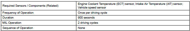
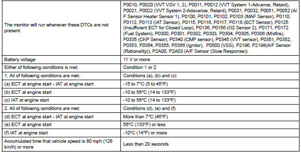
TYPICAL ENABLING CONDITIONS
TYPICAL MALFUNCTION THRESHOLDS
INSPECTION PROCEDURE
HINT: Read freeze frame data using the intelligent tester. The ECM records vehicle and driving condition information as freeze frame data the moment a DTC is stored. When troubleshooting, freeze frame data can be helpful in determining whether the vehicle was running or stopped, whether the engine was warmed up or not, whether the air-fuel ratio was lean or rich, as well as other data recorded at the time of a malfunction
1 CHECK ANY OTHER DTCS OUTPUT (IN ADDITION TO DTC P0128)
- Connect the intelligent tester to the DLC3.
- Turn the ignition switch to the ON position.
- Turn the tester on.
- Select the following menu items: DIAGNOSIS / ENHANCED OBD II / DTC INFO / CURRENT CODES.
- Read the DTCs.
Result
HINT: If any DTCs other than P0128 are output, troubleshoot those DTCs first.
2 CHECK COOLING SYSTEM
- Check for defects in the cooling system that might cause the system to be too cold, such as abnormal radiator fan operation or any modifications.
3 INSPECT THERMOSTAT
- Remove the thermostat.
- Check the valve opening temperature of the thermostat.
Standard: 80 to 84C (176 to 183F)
HINT: In addition to the above check, confirm that the valve is completely closed when the temperature is below the standard.
- Reinstall the thermostat
REPLACE ECM
 Insufficient Coolant Temperature for Closed
Loop Fuel Control
Insufficient Coolant Temperature for Closed
Loop Fuel Control
DTC P0125 Insufficient Coolant Temperature for Closed
Loop Fuel Control
DESCRIPTION
Refer to DTC P0115
DTC No.
DTC Detection Condition
Trouble Area
P0125
E ...
 Oxygen Sensor Circuit Malfunction/ Oxygen Sensor Circuit Low Voltage/ Oxygen
Sensor Circuit High Voltage
Oxygen Sensor Circuit Malfunction/ Oxygen Sensor Circuit Low Voltage/ Oxygen
Sensor Circuit High Voltage
DTC P0136 Oxygen Sensor Circuit Malfunction (Bank 1
Sensor 2)
DTC P0137 Oxygen Sensor Circuit Low Voltage (Bank 1
Sensor 2)
DTC P0138 Oxygen Sensor Circuit High Voltage (Bank 1
Sensor 2)
DTC P01 ...
Other materials:
Inspection
1. INSPECT BRAKE DRUM INSIDE DIAMETER
(a) Using a brake drum gauge or equivalent, measure
the inside diameter of the drum.
Standard inside diameter:
254.0 mm (10.00 in.)
Maximum inside diameter:
256.0 mm (10.08 in.)
2. INSPECT REAR DRUM BRAKE SHOE LINING THICKNESS
(a) Using a ruler, ...
Operation check
1. NOTICE WHEN CHECKING THE FOLLOWING
Power door lock/unlock function:
The wireless door lock control function operates
only when the following 3 conditions are met:
No key is inserted in the ignition key cylinder.
All the doors are closed.
The power door lock sys ...
Power Slide Door Pulse Sensor Malfunction on
Rear Right Door
DTC B2223 Power Slide Door Pulse Sensor Malfunction on
Rear Right Door
DESCRIPTION
A pulse sensor is built into slide door RH for jam and foreign
object detection and for slide door position
detection. The jam and foreign object detection feature of the pulse sensor
monitors the ...
