Toyota Sienna Service Manual: Insufficient Coolant Temperature for Closed Loop Fuel Control
DTC P0125 Insufficient Coolant Temperature for Closed Loop Fuel Control
DESCRIPTION
Refer to DTC P0115
|
DTC No. |
DTC Detection Condition |
Trouble Area |
|
P0125 |
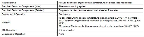
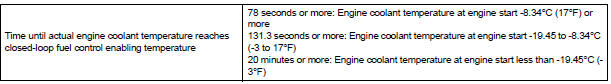
Engine coolant temperature (ECT) does not reach closed-loop enabling temperature for 20 minutes (this period varies with engine start ECT) |
|
MONITOR DESCRIPTION
The resistance of the ECT sensor varies in proportion to the actual ECT. The ECM supplies a constant voltage to the sensor and monitors the signal output voltage of the sensor. The signal voltage output varies according to the changing resistance of the sensor. After the engine is started, the ECT is monitored through this signal. If the ECT sensor indicates that the engine is not yet warm enough for closed-loop fuel control, despite a specified period of time having elapsed since the engine was started, the ECM interprets this as a malfunction in the sensor or cooling system and sets the DTC.
Example: The ECT is 0C (32F) at engine start. After 5 minutes running time, the ECT sensor still indicates that the engine is not warm enough to begin closed-loop fuel (air-fuel ratio feedback) control. The ECM interprets this as a malfunction in the sensor or cooling system and sets the DTC.
MONITOR STRATEGY
TYPICAL ENABLING CONDITIONS
TYPICAL MALFUNCTION THRESHOLDS
WIRING DIAGRAM
Refer to DTC P0115
INSPECTION PROCEDURE
HINT:
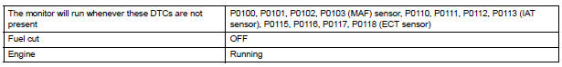
- If any of DTCs P0115, P0116, P0117 or P0118 are set simultaneously with DTC P0125, the Engine Coolant Temperature (ECT) sensor may have an open or a short circuit. Troubleshoot those DTCs first.
- Read freeze frame data using the intelligent tester. The ECM records vehicle and driving condition information as freeze frame data the moment a DTC is stored. When troubleshooting, freeze frame data can be helpful in determining whether the vehicle was running or stopped, whether the engine was warmed up or not, whether the air-fuel ratio was lean or rich, as well as other data recorded at the time of a malfunction.
1 CHECK ANY OTHER DTCS OUTPUT (IN ADDITION TO DTC P0125)
- Connect the intelligent tester to the DLC3.
- Turn the ignition switch to the ON position.
- Turn the tester on.
(d) Select the following menu items: DIAGNOSIS / ENHANCED OBD II / DTC INFO / CURRENT CODES.
- Read the DTCs.
Result

HINT: If any DTCs other than P0125 are output, troubleshoot those DTCs first.
2 INSPECT THERMOSTAT
- Remove the thermostat.
- Check the valve opening temperature of the thermostat.
Standard: 80 to 84C (176 to 183F)
HINT: In addition to the above check, confirm that the valve is completely closed when the temperature is below the standard.
- Reinstall the thermostat
3 CHECK COOLING SYSTEM
- Check for defects in the cooling system that might cause the system to be too cold, such as abnormal radiator fan operation or any modifications.
REPLACE ENGINE COOLANT TEMPERATURE SENSOR
 Throttle / Pedal Position Sensor / Switch "A"
Circuit Range / Performance Problem
Throttle / Pedal Position Sensor / Switch "A"
Circuit Range / Performance Problem
DTC P0121 Throttle / Pedal Position Sensor / Switch "A"
Circuit Range / Performance Problem
HINT:
This DTC relates to the Throttle Position (TP) sensor.
DESCRIPTION
Refer to DTC P0120
...
 Coolant Thermostat (Coolant Temperature
Below Thermostat Regulating Temperature)
Coolant Thermostat (Coolant Temperature
Below Thermostat Regulating Temperature)
DTC P0128 Coolant Thermostat (Coolant Temperature
Below Thermostat Regulating Temperature)
HINT:
This DTC relates to the thermostat.
DESCRIPTION
This DTC is set when the Engine Coolant Temperatur ...
Other materials:
Door Courtesy Switch Circuit
DESCRIPTION
The Multiplex network body ECU detects the condition of the door courtesy
switch assembly.
WIRING DIAGRAM
INSPECTION PROCEDURE
1 READ VALUE OF INTELLIGENT TESTER
Connect the intelligent tester to DLC3.
Turn the ignition switch to ON and push the intelligent
tester ...
Cooling fan motor
On-vehicle inspection
1. No. 1 Cooling fan motor
(A) check that the motor turns smoothly when the
battery is connected to the fan motor connector.
(B) measure the current while the motor is turning.
Standard current:
11.8 To 14.8 A at 20°c (68°f)
if the result is not as specified, r ...
Registration
1. DESCRIPTION OF CODE REGISTRATION
HINT:
The key has 2 codes: The key code (immobiliser code)
and the wireless code. Both of these codes need to be
registered. Refer to page for the wireless code
registration procedures.
When adding master keys or sub keys (Additional
registration) ...
