Toyota Sienna Service Manual: Cranking Holding Function Circuit
DESCRIPTION
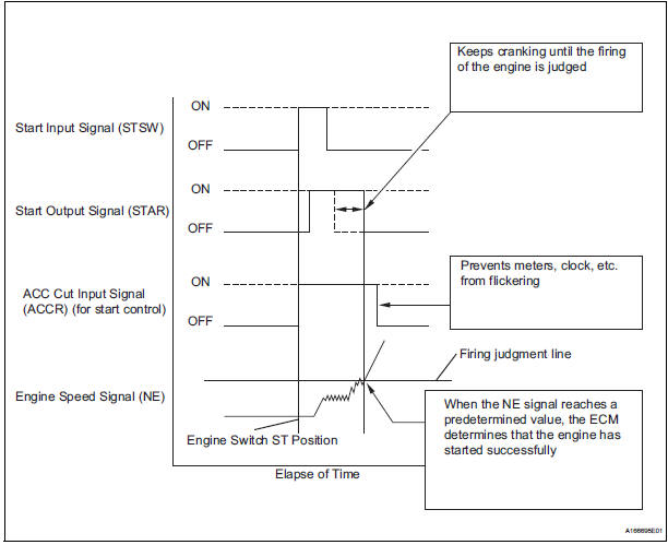
The system detects the ignition switch's starting signal (STSW) and then supplies current to the starter until the ECM judges that the engine has started successfully. The purpose is to reduce the holding time of the ignition key.
WIRING DIAGRAM
Refer to DTC P0617.
INSPECTION PROCEDURE
1 CHECK CRANKING
- When starting the engine, check whether the starter motor starts.
OK: Engine is cranking.
2 READ VALUE OF INTELLIGENT TESTER (STA SIGNAL)
- Connect the intelligent tester to the DLC3.
- Turn the ignition switch to the ON position.
- Turn the tester on.
- Select the following menu items: DIAGNOSIS / ENHANCED OBDII / DATA LIST / ALL / STARTER SIG.
- Check the result when the ignition switch is turned ON and when the engine is started.
OK

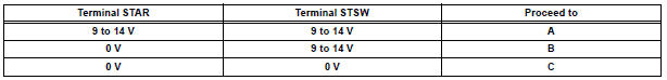
3 CHECK ECM (STAR AND STSW VOLTAGE)
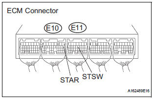
- Measure the voltage between the terminals of the ECM connector and body ground while cranking the engine.
Standard voltage
Result
4 INSPECT PARK/NEUTRAL POSITION SWITCH ASSEMBLY
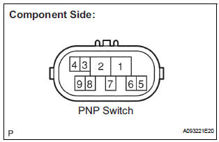
- Inspect the Park/Neutral Position (PNP) switch.
- Disconnect the P1 PNP switch connector.
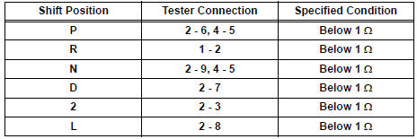
- Measure the resistance according to the value(s) in the table below.
Standard resistance
- Reconnect the PNP switch connector.
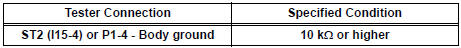
5 CHECK HARNESS AND CONNECTOR (IGNITION SWITCH - PARK/NEUTRAL POSITION SWITCH)
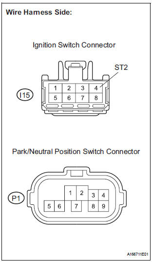
- Disconnect the I15 ignition switch connector.
- Disconnect the P1 park/neutral position switch connector.
- Measure the resistance according to the value(s) in the table below.
Standard resistance (check for open)
Standard resistance (check for short)
- Reconnect the ignition switch connector.
- Reconnect the park/neutral position switch connector.
REPAIR OR REPLACE HARNESS OR CONNECTOR (PARK/NEUTRAL POSITION SWITCH - ECM)
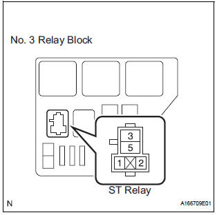
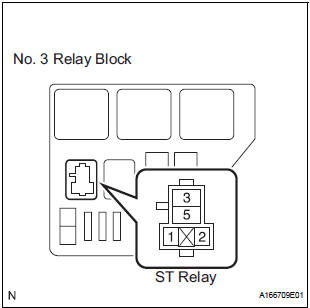
6 INSPECT ST RELAY
- Remove the ST relay from the No. 3 relay block.
- Measure the resistance according to the value(s) in the table below.
Standard resistance
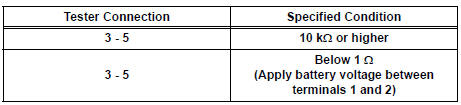
- Reinstall the ST relay to the No. 3 relay block.
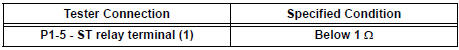
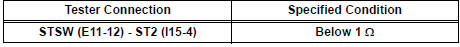
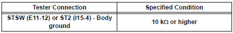
7 CHECK HARNESS AND CONNECTOR (PARK/NEUTRAL POSITION SWITCH - ST RELAY)
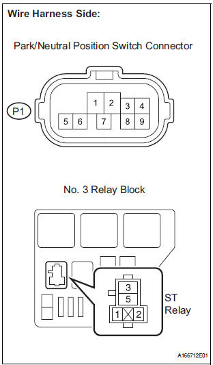
- Disconnect the P1 park/neutral position switch connector.
- Remove the ST relay from the No. 3 relay block.
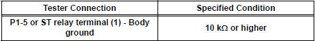
- Measure the resistance according to the value(s) in the table below.
Standard resistance (check for open)
Standard resistance (check for short)
- Reconnect the park/neutral position switch connector.
- Reinstall the ST relay to the No. 3 relay block.
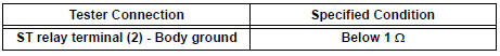
8 CHECK HARNESS AND CONNECTOR (ST RELAY - BODY GROUND)
- Remove the ST relay from the No. 3 relay block.
- Measure the resistance according to the value(s) in the table below.
Standard resistance
- Reinstall the ST relay to the No. 3 relay block.
9 CHECK ST RELAY (POWER SOURCE)
- Remove the ST relay from the No. 3 relay block.
- Measure the voltage according to the value(s) in the table below.
Standard voltage
- Reinstall the ST relay to the No. 3 relay block.
10 INSPECT FUSIBLE LINK
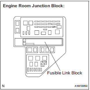
- Remove the fusible link block from the engine room junction block.
- Measure the resistance according to the value(s) in the table below.
Standard resistance
- Reinstall the fusible link block to the engine room junction block
REPAIR OR REPLACE HARNESS OR CONNECTOR (BATTERY - STARTER RELAY)
11 INSPECT STARTER ASSEMBLY
- Inspect the starter assembly
12 CHECK HARNESS AND CONNECTOR (ST RELAY - STARTER ASSEMBLY)
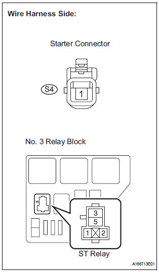
- Remove the ST relay from the No. 3 relay block.
- Disconnect the S4 starter connector.
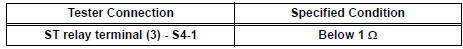
- Measure the resistance according to the value(s) in the table below.
Standard resistance (check for open)
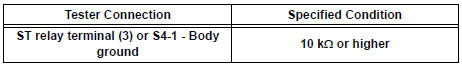
Standard resistance (check for short)
- Reconnect the starter connector.
- Reinstall the ST relay to the No. 3 relay block.
REPAIR OR REPLACE HARNESS OR CONNECTOR (BATTERY - STARTER ASSEMBLY)
13 INSPECT FUSE (ST FUSE)
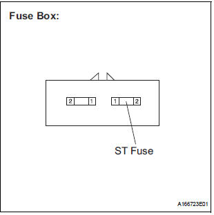
- Remove the ST fuse from the fuse box.
- Measure the resistance according to the value(s) in the table below.
Standard resistance
- Reinstall the ST fuse.
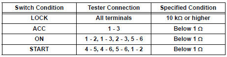
14 INSPECT IGNITION SWITCH ASSEMBLY
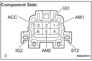
- Disconnect the I15 ignition switch connector.
- Measure the resistance according to the value(s) in the table below.
Standard resistance
- Reconnect the ignition switch connector
15 CHECK HARNESS AND CONNECTOR (ECM - IGNITION SWITCH ASSEMBLY)
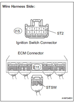
- Disconnect the E11 ECM connector.
- Disconnect the I15 ignition switch connector.
- Measure the resistance according to the value(s) in the table below.
Standard resistance (check for open)
Standard resistance (check for short)
- Reconnect the ECM connector.
- Reconnect the ignition switch connector.
REPAIR OR REPLACE HARNESS OR CONNECTOR (IGNITION SWITCH - BATTERY)
 Fuel Pump Control Circuit
DESCRIPTION
The FUEL PUMP relay switches the fuel pump speed according to the engine
conditions. The fuel pump
operates when the ECM receives the starter-operating signal (STA) and
crankshaft-ro ...
 ACIS Control Circuit
DESCRIPTION
This circuit opens and closes the Intake Air Control Valve (IACV) in response
to changes in the engine
load in order to increase the intake efficiency (ACIS: Acoustic Control
Inducti ...
Other materials:
Stereo Component Amplifier Communication Error
INSPECTION PROCEDURE
1 IDENTIFY THE COMPONENT SHOWN BY THE SUB-CODE
Enter the diagnostic mode.
Press the preset switch "3" to change to "Detailed
Information Mode".
Identify the component shown by the sub-code.
HINT:
"190 (radio receiver ...
Register transmitter id (using intelligent tester)
(a) Connect the intelligent tester to DLC3 (Procedure
"A").
(b) Turn the ignition switch to the ON position
(Procedure "B").
(c) Select the REGIST TIRE following the intelligent
tester screen (UTILITY - REGIST TIRE) (Procedure
"C").
(d) Input the IDs (ID1 t ...
Disassembly
1. REMOVE PROPELLER SHAFT ASSEMBLY
(a) Put matchmarks on both the flanges.
(b) Remove the 4 nuts, bolts and washers.
2. REMOVE INTERMEDIATE SHAFT
(a) Put matchmarks on the propeller shaft subassembly
and universal joint flange.
NOTICE:
Do not use a punch for the marks.
(b) Using a ...
