Toyota Sienna Service Manual: ACIS Control Circuit
DESCRIPTION
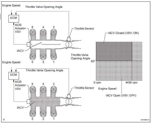
This circuit opens and closes the Intake Air Control Valve (IACV) in response to changes in the engine load in order to increase the intake efficiency (ACIS: Acoustic Control Induction System).
When the engine speed is between 0 and 4450 rpm and the throttle valve opening angle is 60 or more, the ECM supplies current to the VSV (ON status), to close the IACV. Under other conditions, the VSV is usually OFF and the IACV is open.
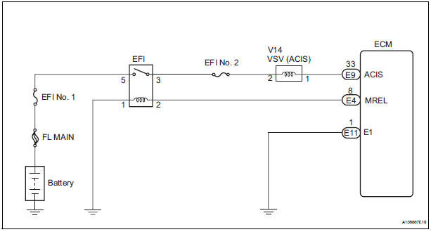
WIRING DIAGRAM
INSPECTION PROCEDURE
1 PERFORM ACTIVE TEST BY INTELLIGENT TESTER (OPERATE VSV FOR ACIS)
- Connect the intelligent tester to the DLC3.
- Start the engine and turn the intelligent tester on.
- Select the following menu items: DIAGNOSIS / ENHANCED OBD II / ACTIVE TEST / INTAKE CTL VSV1. Operate the VSV for AICS.
OK: Operational noise can be heard.
2 CHECK INTAKE AIR CONTROL VALVE (OPERATION)
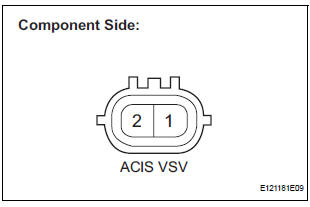
- Disconnect the V14 VSV for ACIS connector.
- Apply battery voltage between the terminals of the air intake valve connector.
- Check the air intake valve operation.
OK: Operational noise can be heard.
- Reconnect the VSV for ACIS connector.
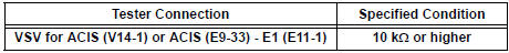
3 CHECK HARNESS AND CONNECTOR (VSV FOR ACIS - ECM)
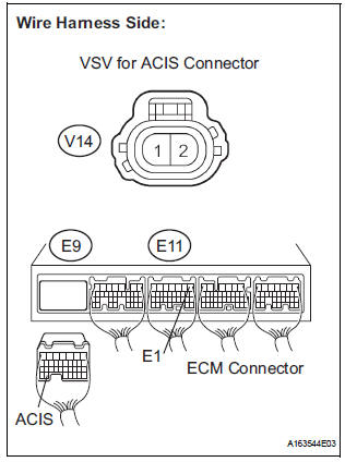
- Check the wire harness and connectors between the VSV for ACIS and ECM.
- Disconnect the V14 VSV for ACIS connector.
- Disconnect the E9 ECM connector.
- Measure the resistance according to the value(s) in the table below.
Standard resistance : Check for open

Check for short
- Reconnect the VSV for ACIS connector.
- Reconnect the ECM connector
4 INSPECT FUSE (EFI NO. 2 FUSE)
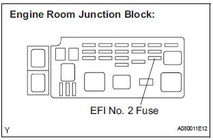
- Check the EFI No. 2 fuse.
- Remove the EFI No. 2 fuse from the engine room junction block.
- Measure the EFI No. 2 fuse resistance.
Standard resistance: Below 1 Ω
- Reinstall the EFI No. 2 fuse.
5 CHECK HARNESS AND CONNECTOR (VSV FOR ACIS - EFI RELAY)
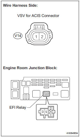
- Check the wire harness between the VSV for ACIS connector and EFI relay.
- Remove the EFI relay from the engine room junction block.
- Disconnect the V14 VSV connector.
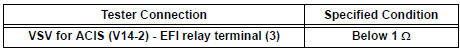
- Measure the resistance according to the value(s) in the table below.
Standard resistance : Check for open
- Reinstall the EFI relay.
- Reconnect the VSV connector.
CHECK ECM POWER SOURCE CIRCUIT
 Cranking Holding Function Circuit
DESCRIPTION
The system detects the ignition switch's starting signal (STSW) and then
supplies current to the starter
until the ECM judges that the engine has started successfully. The purpose is t ...
 Air Intake Control Circuit
DESCRIPTION
The air cleaner is equipped with two inlets, one of which is opened or closed
by the Air Intake Control
Valve (AICV). This system reduces intake noise and increases engine power at
l ...
Other materials:
Removal
HINT:
Use the same procedures for the RH side and LH side.
The procedures listed below are for the LH side.
1. PRECAUTION
CAUTION:
Be sure to read "PRECAUTION" thoroughly before
servicing.
2. DISCONNECT CABLE FROM NEGATIVE BATTERY
TERMINAL
CAUTION:
Wait for 90 s ...
Air-fuel ratio (a/f) and heated oxygen (ho2)
sensor heater monitors (front a/f and rear ho2 sensor
type)
(a) Preconditions
The monitor will not run unless:
The MIL is OFF.
(b) Drive Pattern
(1) Connect an intelligent tester to the DLC3.
(2) Turn the ignition switch to the ON position.
(3) Clear the DTCs.
(4) Start the engine.
(5) Allow the engine to idle for 10 minutes or more.
...
Inspection
1. INSPECT PURGE VSV
(a) Measure the resistance of the purge VSV.
Standard resistance
If the result is not as specified, replace the purge
VSV.
(b) Check the operation of the purge VSV.
(1) Check that air does not flow from port E to port
F.
(2) Apply battery voltage across t ...
