Toyota Sienna Service Manual: Disassembly
1. REMOVE RH SEAT REAR SEAT RECLINING COVER
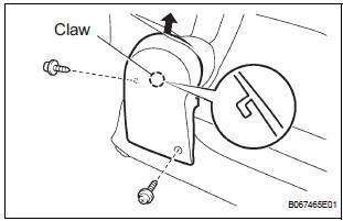
- Remove the 2 screws.
- Remove the RH seat rear seat reclining cover by pulling it out in the arrow mark direction shown in the illustration.
2. REMOVE LH SEAT REAR SEAT RECLINING COVER
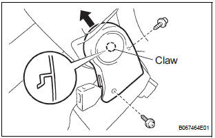
- Remove the 2 screws.
- Remove the LH seat rear seat reclining cover by pulling it out in the arrow mark direction shown in the illustration.
3. REMOVE REAR SEATBACK ASSEMBLY RH
- Disengage the reclining remote control cable.
- Disengage the rear seat lock release strap cable.
- Remove the 4 bolts and rear seatback assembly RH.
4. REMOVE REAR NO. 2 SEAT BELT ASSEMBLY INNER RH
- Remove the bolt and rear No.2 seat belt assembly inner RH.
5. REMOVE NO. 2 REAR SEAT COVER BEZEL
- Remove the 3 screws and No. 2 rear seat cover bezel.
6. REMOVE NO. 2 SEATBACK LOCK CONTROL BEZEL
- Remove the screw and No. 2 seatback lock control bezel.
7. REMOVE NO. 2 SEATBACK COVER RH
- Disengage the claw and remove the 2 headrest supports.
- Remove the hog rings and seatback cover together with the pad.
- Remove the hog rings and No. 2 seatback cover RH.
8. REMOVE REAR SEAT LOCK RELEASE STRAP ASSEMBLY
- Remove the nut and rear seat lock release strap assembly.
9. REMOVE REAR SEAT BACK CONNECTING RH WIRE
- Remove the nut and rear seatback connecting RH wire.
10. REMOVE RECLINING RELEASE HANDLE SUBASSEMBLY RH
- Remove the screw and reclining release handle sub-assembly RH.
11. REMOVE RECLINING ADJUSTER RELEASE HANDLE NO. 2 RH
- Remove the nut and reclining adjuster release handle No.2 RH.
12. REMOVE NO. 2 SEAT CUSHION COVER SUBASSEMBLY RH
- Remove the hog rings and cushion cover together with the pad.
- Remove the hog rings and No. 2 seat cushion cover sub-assembly RH.
13. REMOVE LOCUS CABLE RH
- Remove the nut and locus cable RH.
14. REMOVE NO. 2 SEAT CUSHION SPRING ASSEMBLY RH
15. REMOVE REAR SEAT STAY SUB-ASSEMBLY
- Remove the nut and seat stay sub-assembly.
 Removal
1. REMOVE REAR SEAT LEG SIDE GARNISH SUBASSEMBLY RH
Disengage the clips and remove the seat leg side
garnish sub-assembly RH.
2. REMOVE REAR NO. 2 SEAT ASSEMBLY RH
Remove ...
 Reassembly
1. INSTALL REAR SEAT STAY SUB-ASSEMBLY
Install the seat stay sub-assembly with the nut.
Torque: 5.5 N*m (56 kgf*cm, 49 in.*lbf)
2. INSTALL NO. 2 SEAT CUSHION SPRING ASSEMBLY
RH
3. INS ...
Other materials:
Mute Signal Circuit between Radio and Navigation Assembly and
Television Display Assembly
DESCRIPTION
The radio and navigation assembly controls the volume according to the MUTE
signal from the television
display assembly.
The MUTE signal is sent to reduce noise and a popping sound generated when
switching the mode, etc.
If there is an open in the circuit, noise can be heard ...
Freeze frame data
1. FREEZE FRAME DATA
(a) Whenever a DTC is detected or the ABS operates,
the skid control ECU stores the current vehicle
(sensor) state as freeze frame data.
The skid control ECU stores the number of times
(maximum: 31) the ignition switch has been turned
from OFF to the ON position since th ...
System description
1. GENERAL
In conjunction with impact absorbing structure for a
frontal collision, the SRS (Supplemental Restraint
System) driver airbag and front passenger airbag
were designed to supplement seat belts in the event
of a frontal collision in order to help reduce shock to
the head ...
