Toyota Sienna Service Manual: Cruise Main Indicator Light Circuit
DESCRIPTION
- The ECM detects a cruise control switch signal and sends it to the combination meter through CAN and BEAN. Then the CRUISE main indicator light comes on.
- The CRUISE main indicator light circuit uses CAN and BEAN for communication. If there is a malfunction in this circuit, check for DTCs in the CAN communication system and multiplex communication system before troubleshooting this circuit.
INSPECTION PROCEDURE
1 PERFORM ACTIVE TEST BY INTELLIGENT TESTER
- Connect the intelligent tester to the DLC3.
- Turn the ignition switch to the ON position and turn the intelligent tester main switch on.
- Check the CRUISE main indicator light by performing the ACTIVE TEST.
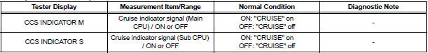
METER:

OK: The indicator light blinks/goes off.
2 READ VALUE OF INTELLIGENT TE
- Connect the intelligent tester to the DLC3.
- Turn the ignition switch to the ON position and turn the intelligent tester main switch on.
- Check the DATA LIST for proper functioning of the CRUISE main indicator light.
ECM (Cruise control):
OK: When the cruise control main switch is operated, the display changes as shown above.
PROCEED TO NEXT CIRCUIT INSPECTION SHOWN IN PROBLEM SYMPTOMS TABLE
 Cruise Control Switch Circuit
DESCRIPTION
The cruise control main switch operates 7 functions: SET, - (COAST),
TAP-DOWN, RES (RESUME), +
(ACCEL), TAP-UP, and CANCEL. The SET, TAP-DOWN, and - (COAST) functions, and the
RES
( ...
 TC and CG Terminal Circuit
DESCRIPTION
Connecting terminals TC and CG of the DLC3 causes the system to enter the
self-diagnostic mode. If a
malfunction is present, DTCs will be output.
HINT:
When a particular warning li ...
Other materials:
CD Abnormal/ Excess Current/ Tray Insertion / Ejection Error/ CD Abnormal/
Excess Current/ Tray Insertion / Ejection Error
DTC 62-44 CD Abnormal
DTC 62-48 Excess Current
DTC 62-50 Tray Insertion / Ejection Error
DTC 63-44 CD Abnormal
DTC 63-48 Excess Current
DTC 63-50 Tray Insertion / Ejection Error
DESCRIPTION
DTC No.
DTC Detecting Condition
Trouble Area
62-44
Operation error ...
Installation
HINT:
Use the same procedures for the RH side and LH side.
The procedures listed below are for the LH side.
1. INSTALL FRONT AIRBAG SENSOR LH
Check that the ignition switch is off.
Check that the battery negative (-) terminal is
disconnected.
CAUTION: ...
Problem symptoms table
HINT:
Proceed to the troubleshooting for each circuit in the table
below.
AIRBAG SYSTEM
Symptom
Suspected Area
The SRS warning light goes off after the primary
check, but then comes on.
SRS Warning Light Remains ON
When the ignition switch is turned to t ...
