Toyota Sienna Service Manual: TC and CG Terminal Circuit
DESCRIPTION
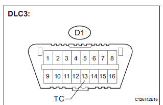
Connecting terminals TC and CG of the DLC3 causes the system to enter the self-diagnostic mode. If a malfunction is present, DTCs will be output.
HINT: When a particular warning light remains blinking, a ground short in the wiring of terminal TC of the DLC3 or an internal ground short in the relevant ECU is suspected.
WIRING DIAGRAM
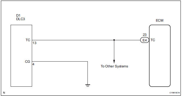
INSPECTION PROCEDURE
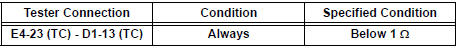
1 CHECK HARNESS AND CONNECTOR (TERMINAL TC of DLC3 - ECM)
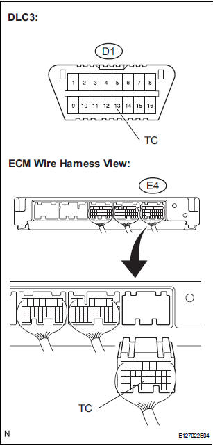
- Disconnect the E4 connector from the ECM.
- Measure the resistance according to the value(s) in the table below.
Standard resistance
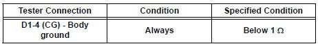
2 CHECK HARNESS AND CONNECTOR (TERMINAL CG of DLC3 - BODY GROUND)
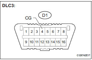
- Measure the resistance according to the value(s) in the table below.
Standard resistance
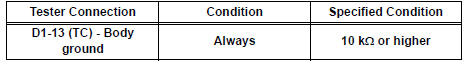
3 CHECK HARNESS AND CONNECTOR (TERMINAL TC of DLC3 - BODY GROUND)
- Measure the resistance according to the value(s) in the table below.
Standard resistance
PROCEED TO NEXT CIRCUIT INSPECTION SHOWN IN PROBLEM SYMPTOMS TABLE
 Cruise Main Indicator Light Circuit
DESCRIPTION
The ECM detects a cruise control switch signal and sends it to the
combination meter through CAN
and BEAN. Then the CRUISE main indicator light comes on.
The CRUISE ...

Other materials:
Steering Angle Sensor Circuit Malfunction
DTC C1231/31 Steering Angle Sensor Circuit Malfunction
DESCRIPTION
The steering angle sensor signal is sent to the skid control ECU through the
CAN communication system.
When there is a malfunction in the communication, it will be detected by the
diagnosis function.
WIRING DIAGRAM
INS ...
Terminals of ECU
1. MULTIPLEX NETWORK GATEWAY ECU
Disconnect the G4 ECU connector.
Measure the voltage between the specified
terminals on the wire harness side connector.
If the result is not as specified, there may be a
malfunction on the wire harness side.
Measure the resistance between ...
Installing the spare tire
Remove any dirt or foreign matter
from the wheel contact surface.
If foreign matter is on the wheel
contact surface, the wheel nuts
may loosen while the vehicle is in
motion, causing the tire to come
off.
Install the tire and loosely
tighten each wheel nut by hand
by ...
