Toyota Sienna Service Manual: Removal
1. DISCONNECT CABLE FROM NEGATIVE BATTERY TERMINAL
2. REMOVE AIR FUEL RATIO SENSOR (for Bank 2 Sensor 1)
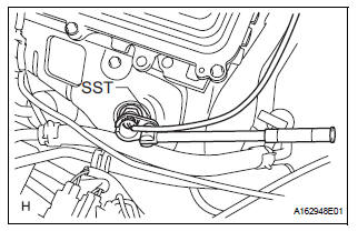
(a) Disconnect the sensor connector.
(b) Using SST, remove the sensor from the exhaust manifold.
SST 09224-00010
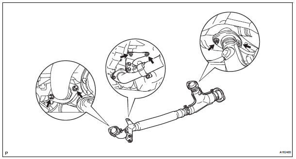
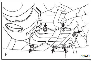
3. REMOVE FRONT EXHAUST PIPE ASSEMBLY
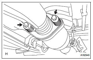
(a) Disconnect the heated oxygen sensor (for Bank 1 Sensor 2) connector under the center console.
(b) Remove the 2 bolts and 2 compression springs.
(c) Remove the 6 nuts and front exhaust pipe assembly.
4. REMOVE EXHAUST MANIFOLD RH
(a) Remove the nut, bolt and exhaust manifold stay.
(b) Disconnect the air fuel ratio sensor (for Bank 1 Sensor 1) connector.
(c) Remove the 6 nuts and exhaust manifold RH.
(d) Remove the gasket and exhaust manifold to head gasket.
5. REMOVE AIR FUEL RATIO SENSOR (for Bank 1 Sensor 1)
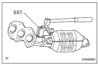
(a) Using SST, remove the sensor.
SST 09224-00010
 On-vehicle inspection
HINT:
The type of ignition switch on this model differs according to
the specifications of the vehicle. For the expressions used in
this section, refer to the "EXPRESSIONS OF IGNITION
SWITCH& ...
 Inspection
1. INSPECT AIR FUEL RATIO SENSOR
(a) Measure the resistance of the sensor.
Standard resistance
If the resistance is not as specified, replace the
sensor. ...
Other materials:
Diagnosis system
1. CHECK DLC3
The ECU uses ISO 15765-4 for communication.
The terminal arrangement of the DLC3 complies
with SAE J1962 and meets the ISO 15765-4 format.
NOTICE:
*: Before measuring the resistance, leave the
vehicle as is for at least 1 minute and do not
operate the ignition s ...
Mobile Assistant
The Mobile Assistant feature will activate Apple’s Siri® Eyes Free mode via
the steering wheel switches. To operate the Mobile Assistant, a compatible
cellular phone must be registered and connected to this system via Bluetooth®.
Press and hold the until
you hear the beeps
...
SRS airbags
The SRS airbags inflate when the vehicle is subjected to certain
types of severe impacts that may cause significant injury to the
occupants. They work together with the seat belts to help reduce
the risk of death or serious injury.
SRS front airbags
SRS driver airbag/front passenger ...
