Toyota Sienna Service Manual: Data list / active test
1. USING INTELLIGENT TESTER
- Connect the intelligent tester to the DLC3.
- Monitor the ECU data by following the prompts on the tester screen.
HINT: The intelligent tester has a "Snapshot" function which records the monitored data. Refer to the intelligent tester operator's manual for further details.
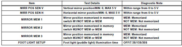
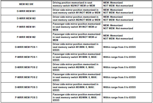
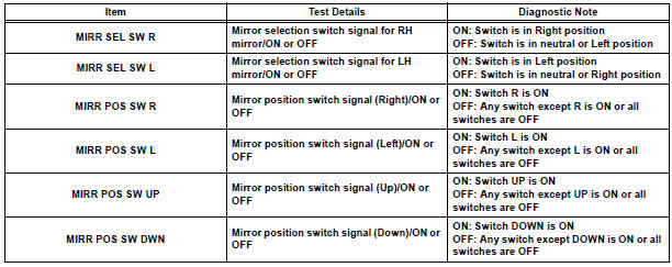
2. DATA LIST
HINT: Using the DATA LIST displayed on the intelligent tester, you can read the value of the switch, sensor, actuator, etc. without parts removal. Reading the DATA LIST as the first step of troubleshooting is one way to shorten the labor time.
- Connect the intelligent tester to the DLC3.
- Ignition switch on.
- Enter the following menus: DIAGNOSIS / ENHANCED OBD II / DATA LIST.
- Read the DATA LIST according to the display on the tester.
MIRROR-L/MIRROR-R
D-SEAT
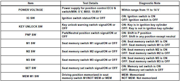
BODY
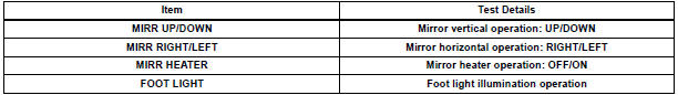
3. ACTIVE TEST
HINT: Performing the ACTIVE TEST using the intelligent tester allows you to operate the relay, VSV, actuator, etc.
without parts removal. Performing the ACTIVE TEST as the first step of troubleshooting is one way to shorten the labor time. It is possible to display the DATA LIST during the ACTIVE TEST.
- Connect the intelligent tester to the DLC3.
- Ignition switch on.
- Enter the following menus: DIAGNOSIS / ENHANCED OBD II / ACTIVE TEST.
- Perform the ACTIVE TEST according to the display on the tester.
MIRROR-L/MIRROR-R
 Diagnosis system
1. DESCRIPTION
When troubleshooting a vehicle with the diagnosis
system, the only difference from the usual
troubleshooting procedure is connecting the
intelligent tester to the vehicl ...
 On-vehicle inspection
1. CHECK POWER MIRROR SWITCH OPERATION
Remote control
The mirror adjust switch can control the adjustment
axis of the mirror surface.
Reverse-linked
This function tilts the mir ...
Other materials:
Short in Side Squib RH Circuit
DTC B0110/43 Short in Side Squib RH Circuit
DESCRIPTION
The side squib RH circuit consists of the center airbag sensor assembly and
the front seat side airbag
assembly RH.
The circuit instructs the SRS to deploy when deployment conditions are met.
DTC B0110/43 is recorded when a short cir ...
Precaution
1. HANDLING PRECAUTIONS ON STEERING SYSTEM
(a) Be careful to replace the parts properly because
they could affect the performance of the steering
system and result in a driving hazard.
2. HANDLING PRECAUTIONS ON SRS AIRBAG
SYSTEM
(a) The SIENNA is equipped with SRS (Supplemental
Restraint Sys ...
BluetoothÂź Audio
Listening to BluetoothÂź Audio
The BluetoothÂź audio system enables the user to enjoy music
played on a portable player from the vehicle speakers via wireless
communication.
When a BluetoothÂź device cannot be connected, check the connection
status on the âBluetooth* Audioâ screen. If the ...
