Toyota Sienna Service Manual: Data list / active test
1. DATA LIST
HINT: Using the DATA LIST displayed on the intelligent tester, you can read the value of the switch, sensor, actuator, etc. without parts removal. Reading the DATA LIST as the first step of troubleshooting is one way to shorten the labor time.
- Connect the intelligent tester to the DLC3.
- Turn the ignition switch ON.
- Read the DATA LIST according to the display on the tester.
Power back door ECU
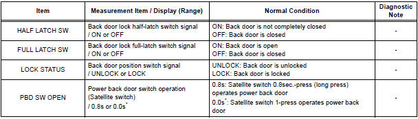
* "0.0s" appearing on the display of the intelligent tester means that a 1-press of the satellite switch operates the power back door.
2. ACTIVE TEST
HINT: Performing the ACTIVE TEST using the intelligent tester allows you to operate the relay, VSV, actuator, etc.
without parts removal. Performing the ACTIVE TEST as the first step of troubleshooting is one way to shorten the labor time. It is possible to display the DATA LIST during the ACTIVE TEST.
- Connect the intelligent tester to the DLC3.
- Turn the ignition switch ON.
- Perform the ACTIVE TEST according to the display on the tester.
Power back Door ECU

 DTC check / clear
1. CHECK DTC (USING INTELLIGENT TESTER)
Checking DTCs.
Connect the intelligent tester to the DLC3.
Turn the ignition switch ON.
Read DTCs by following the pro ...
 Diagnostic trouble code chart
If a malfunction code is displayed during the DTC check,
check the circuit listed for that code in the table below.
(Proceed to the page given for that circuit.)
BACK DOOR CLOSER SYSTEM
...
Other materials:
Disposal
HINT:
When scrapping a vehicle equipped with the SRS or
disposing of the steering pad, be sure to deploy the airbag
first in accordance with the procedure described below. If any
abnormality occurs with airbag deployment, contact the
SERVICE DEPT. of TOYOTA MOTOR SALES, U.S.A., INC.
CAUTION:
...
Communication Error from Distance Control
ECU to ECM
DTC P1615 Communication Error from Distance Control
ECU to ECM
DTC U1101 Lost Communication with Distance Control
ECU
DESCRIPTION
The distance control ECU receives information about the area in front of the
vehicle from the laser sensor
and then sends a brake control demand signal (decelerat ...
Cruise Control Switch Circuit
DESCRIPTION
The cruise control main switch operates 8 functions: SET, - (COAST),
TAP-DOWN, RES (RESUME), +
(ACCEL), TAP-UP, CANCEL, and MODE. The SET, TAP-DOWN, and - (COAST) functions,
and the RES
(RESUME), TAP-UP, and + (ACCEL) functions are operated with the same switch. The
cruise contr ...
