Toyota Sienna Service Manual: Inspection
1. INSPECT PARK/NEUTRAL POSITION SWITCH ASSEMBLY OPERATION
(a) Apply the parking brake and turn the ignition switch to the ON position.
(b) Depress the brake pedal and check that the engine starts only when the shift lever is in the N or P position and the engine does not start when the shift lever is in other positions.
(c) Check that the back up light comes on and the reverse warning buzzer sounds only when the shift lever is in the R position and the light and buzzer do not operate when the shift lever is in other positions.
(d) If a failure is found, check the park/neutral position switch for continuity.
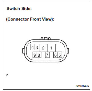
2. INSPECT PARK/NEUTRAL POSITION SWITCH ASSEMBLY
(a) Jack up the vehicle.
(b) Disconnect the park/neutral position switch connector.
(c) Measure the resistance according to the value(s) in the table below when the shift lever is moved to each position.
Resistance 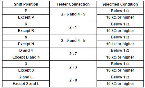
ADJUSTMENT
1. ADJUST PARK/NEUTRAL POSITION SWITCH ASSEMBLY
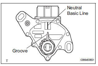
(a) Loosen the 2 bolts of the park/neutral position switch and move the shift lever to the N position.
(b) Align the groove with the neutral basic line.
(c) Hold the switch in position and tighten the 2 bolts.
Torque: 5.4 N*m (55 kgf*cm, 48 in.*lbf) (d) After adjustment, perform the inspection described in park/neutral position switch assembly operation.
 Removal
1. REMOVE BATTERY
2. REMOVE AIR CLEANER ASSEMBLY
HINT:
(See page EM-26)
3. SEPARATE TRANSMISSION CONTROL CABLE ASSEMBLY
(a) Remove the nut from the control shaft lever.
(b) Disconnect the ...
 Installation
1. INSTALL PARK/NEUTRAL POSITION SWITCH ASSEMBLY
(a) Install the park/neutral position switch to the manual
valve shaft.
(b) Temporarily install the 2 bolts.
(c) Place a new lock plate a ...
Other materials:
General information
A large number of ECU controlled systems are used in the
SIENNA. In general, ECU controlled systems are considered
to be very intricate, requiring a high level of technical
knowledge to troubleshoot. However, most problem checking
procedures only involve inspecting the ECU controlled
system's c ...
Rear evaporator temperature sensor circuit
DESCRIPTION
The rear evaporator temperature sensor is installed on the rear evaporator.
It detects the rear evaporator
temperature. The sensor sends a signal to the A/C amplifier. The resistance of
the rear evaporator
temperature sensor changes in accordance with the rear evaporator temperatu ...
Removal
1. PRECAUTION
CAUTION:
Be sure to read "PRECAUTION" thoroughly before
servicing.
2. DISCONNECT CABLE FROM NEGATIVE BATTERY
TERMINAL
CAUTION:
Wait for 90 seconds after disconnecting the cable to
prevent the airbag working.
3. REMOVE INSTRUMENT PANEL FINISH PANEL SUBASSEMBLY LOWER L ...
