Toyota Sienna Service Manual: Diagnosis system
1. CHECK DLC3
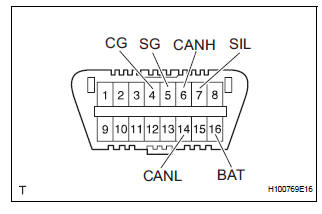
(a) The vehicle's ECM uses the ISO 15765-4 for communication. The terminal arrangement of the DLC3 complies with SAE J1962 and matches the ISO 15765-4 format.
HINT: Connect the cable of the intelligent tester to the DLC3, turn the ignition switch to the ON position and attempt to use the tester. If the display indicates that a communication error has occurred, there is a problem either with the vehicle or with the tester.
If communication is normal when the tester is connected to another vehicle, inspect the DLC3 of the original vehicle.
If communication is still not possible when the tester is connected to another vehicle, the problem may be in the tester itself. Consult the Service Department listed in the tester's instruction manual.

NOTICE: *: Before measuring the resistance, leave the vehicle as is for at least 1 minute and do not operate the ignition switch, any other switches or the doors.
 Terminals of ecu
1. A/C AMPLIFIER
(a) Waveform 1:
(b) Waveform 2:
(c) Waveform 3: ...
 Dtc check / clear
1. DTC CHECK (SENSOR CHECK)
(a) After the indicator check is completed, the system
enters the DTC check mode automatically.
(b) Read the codes displayed on the panel. Refer to the
list of co ...
Other materials:
Side Airbag Sensor Assembly LH Circuit Malfunction
DTC B1141/33 Side Airbag Sensor Assembly LH Circuit Malfunction
DESCRIPTION
The side airbag sensor LH circuit consists of the center airbag sensor
assembly and side airbag sensor
LH.
If the center airbag sensor assembly receives signals from the side airbag
sensor LH, it judges whether or
...
On-vehicle inspection
1. Inspect intake air surge tank assembly
(A) inspection procedure when applying voltage
between the terminals:
(1) Disconnect the connector from the intake air
control valve.
(2) Apply battery voltage between terminals 1 (-)
and 2 (+) of the intake air control valve. Check
that a click ...
Data list / active test
1. READ DATA LIST
HINT:
Using the intelligent tester to read the Data List allows
the values or states of switches, sensors, actuators and
other items to be read without removing any parts. This
non-intrusive inspection can be very useful because
intermittent conditions or signals may be disco ...
