Toyota Sienna Service Manual: ABS Warning Light does not Come ON
WIRING DIAGRAM
See page BC-47.
INSPECTION PROCEDURE
1 INSPECT ABS WARNING LIGHT
(a) Disconnect the skid control ECU connector.
(b) Turn the ignition switch to the ON position.
(c) Check that the ABS warning light comes on.
OK: ABS warning light comes on.
HINT: If troubleshooting has been carried out according to the PROBLEM SYMPTOMS TABLE, refer back to the table and proceed to the next step (See page BC-7).

REPLACE BRAKE ACTUATOR ASSEMBLY
2 CHECK HARNESS AND CONNECTOR (BETWEEN SKID CONTROL ECU AND COMBINATION METER ASSEMBLY)
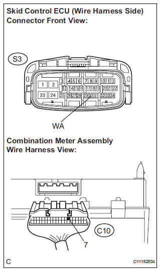
(a) Turn the ignition switch off.
(b) Disconnect the combination meter connector.
(c) Measure the resistance according to the value(s) in the table below.
Standard resistance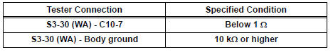

3 INSPECT COMBINATION METER ASSEMBLY
(a) Check the combination meter (See page ME-4).
HINT: If troubleshooting has been carried out according to the PROBLEM SYMPTOMS TABLE, refer back to the table and proceed to the next step (See page BC-7).
END
 ABS Warning Light Remains ON
DESCRIPTION
If any of the following is detected, the ABS warning light remains on.
The skid control ECU connectors are disconnected from the skid control
ECU.
There is a malfunction in the s ...
 Brake Warning Light Remains ON
DESCRIPTION
If the ECU detects a trouble, it turns on the brake warning light at the same
time of prohibiting ABS
control.
At this time, the ECU records a DTC in memory.
Connect terminals TC ...
Other materials:
Removal
1. REMOVE ENGINE AND TRANSAXLE
HINT:
(See page EM-26)
2. REMOVE AUTOMATIC TRANSMISSION WITH
TRANSFER
HINT:
(See page AX-164)
3. REMOVE TRANSFER ASSEMBLY
HINT:
(See page TF-8)
4. REMOVE CTR DIFFERENTIAL LOCK SLEEVE
HINT:
(See page TF-13)
5. REMOVE TRANSFER CASE OIL SEAL
(a) Using SS ...
TRAC OFF Indicator Light does not Come ON
DESCRIPTION
The skid control ECU is connected to the combination meter via CAN and
multiplex communications.
When the traction OFF switch is turned on, the TRAC OFF indicator light will
come on (for 2WD model).
WIRING DIAGRAM
Refer to TRAC OFF Indicator Light Remains ON (See page BC-157).
...
Installation
1. Install generator assembly
(a) Install the bracket with the bolt.
Torque: 20 N*m (204 kgf*cm, 15 ft.*lbf)
(b) Install the wire harness clamp stay.
Torque: 8.4 N*m (86 kgf*cm, 74 in.*lbf)
(c) Connect the wire harness clamp.
(d) Install the generator assembly to the cylinder ...
