Toyota Sienna Service Manual: Shift Solenoid "E" Control Circuit
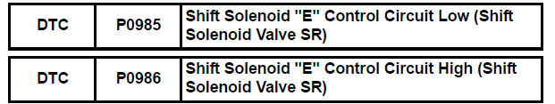
DESCRIPTION
Shifting from 1st to 5th is performed in combination with "ON" and "OFF"
operation of the shift solenoid
valves SL1, SL2, SL3, S4 and SR which are controlled by the ECM. If an open or
short circuit occurs in
either of the shift solenoid valves, the ECM controls the remaining normal shift
solenoid valves to allow
the vehicle to be operated smoothly (Fail safe function).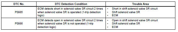
MONITOR DESCRIPTION
The ECM commands gear shifts by turning the shift solenoid valves "ON/OFF". When there is an open or short circuit in any shift solenoid valve circuit, the ECM detects the problem and illuminates the MIL and stores the DTC. And the ECM performs the fail-safe function and turns the other normal shift solenoid valves "ON/OFF" (In case of an open or short circuit, the ECM stops sending current to the circuit.) (See page AX-30).
MONITOR STRATEGY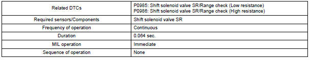
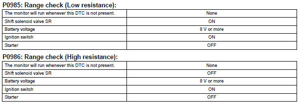
TYPICAL ENABLING CONDITIONS
TYPICAL MALFUNCTION THRESHOLDS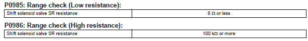
COMPONENT OPERATING RANGE
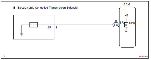
WIRING DIAGRAM
INSPECTION PROCEDURE
1 INSPECT TRANSMISSION WIRE (SR)
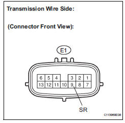
(a) Disconnect the transmission wire connector from the transaxle.
(b) Measure the resistance according to the value(s) in the table below.
Standard resistance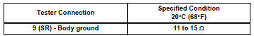

2 CHECK HARNESS AND CONNECTOR (TRANSMISSION WIRE - ECM)
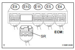
(a) Connect the transmission wire connector to the transaxle.
(b) Disconnect the connector from the ECM.
(c) Measure the resistance according to the value(s) in the table below.
Standard resistance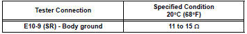

REPLACE ECM
3 INSPECT SHIFT SOLENOID VALVE SR
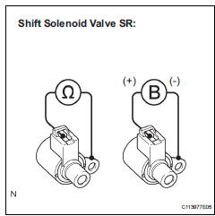
(a) Remove the shift solenoid valve SR.
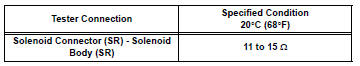
(b) Measure the resistance according to the value(s) in the table below.
Standard resistance
(c) Connect the positive (+) lead to the terminal of the solenoid connector, and the negative (-) lead to the solenoid body.
OK: The solenoid makes an operating sound.

REPAIR OR REPLACE TRANSMISSION WIRE
 Shift Solenoid "D" Control Circuit
DESCRIPTION
Shifting from 1st to 5th is performed in combination with "ON" and "OFF"
operation of the shift solenoid
valves SL1, SL2, SL3, S4 and SR which are controlled by ...
 Pressure Control Solenoid "D" Performance (Shift
Solenoid Valve SLT)
Pressure Control Solenoid "D" Performance (Shift
Solenoid Valve SLT)
SYSTEM DESCRIPTION
The linear solenoid valve (SLT) controls the transmission line pressure for
smooth transmission operation
based on signals from the throttle position sensor and the vehicle spee ...
Other materials:
Auto Up / Down Function does not Operate
DESCRIPTION
If the AUTO UP/DOWN function does not operate, any of the following troubles
may be the cause:
When the PWR fuse or the power window relay (Marking: PWR) is
replaced with new ones, or when
the battery terminal and the connector of the power window master switch are
d ...
Audio terminal
COMPONENTS
REMOVAL
1. REMOVE INSTRUMENT CLUSTER CENTER NO. 2 FINISH PANEL
Using a moulding remover, disengage the 3 clips.
Disconnect the connector and remove the
instrument cluster center No. 2 finish panel.
2. REMOVE STEREO JACK ADAPTER ASSEMBLY
Disenga ...
Turning on the high beam headlights
With the headlights on, push
the lever away from you to turn
on the high beams.
When the light switch is in
position, the Automatic High Beam
system will be activated.
Pull the lever toward you to the
center position to turn the high
beams off.
Pull the lever toward you and ...
