Toyota Sienna Service Manual: Diagnosis system
1. CHECK DLC3
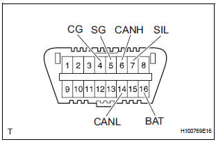
- The ECU uses ISO 15765-4 for communication.
The terminal arrangement of the DLC3 complies with SAE J1962 and meets the ISO 15765-4 format.
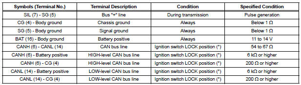
NOTICE: *: Before measuring the resistance, leave the vehicle as is for at least 1 minute and do not operate the ignition switch, any other switches, or the doors. If the result is not as specified, the DLC3 may have a malfunction. Repair or replace the harness and connector.
HINT: If the display shows a communication error message when connecting the cable of the intelligent tester to the DLC3, turning the ignition switch to the ON position and operating the intelligent tester, there is a problem on the vehicle side or tool side.
- If communication is normal when the tool is connected to another vehicle, inspect the DLC3 on the original vehicle.
- If communication is still not possible when the tool is connected to another vehicle, the problem is probably in the tool itself. Consult the Service Department listed in the tool's instruction manual.
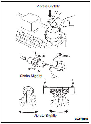
2. SYMPTOM SIMULATION
HINT:
The most difficult case in troubleshooting is when no symptoms occur. In such cases, a thorough customer problem analysis must be carried out. Then the same or similar conditions and environment in which the problem occurred in the customer's vehicle should be simulated.
No matter how experienced or skilled a technician may be, if he proceeds to troubleshoot without confirming the problem symptoms, he will likely overlook something important and make a wrong guess at some points in the repair operation.
This leads to a standstill in troubleshooting.
- Vibration method: When vibration seems to be the major cause.
HINT: Perform the simulation method only during the primary check period (for approximately 6 seconds after the ignition switch is turned to the ON position).
- Slightly vibrate the part of the sensor considered
to be the problem cause with your fingers and
check whether the malfunction occurs.
HINT: Shaking the relays too strongly may result in open relays.
- Slightly shake the connector vertically and horizontally.
- Slightly shake the wire harness vertically and horizontally.
The connector joint and fulcrum of the vibration are the major areas to be checked thoroughly.
- Simulation method for DTC B1795: Turn the ignition
switch from the LOCK to the ON position, hold for
10 seconds, and then back to the LOCK position
again 50 times in a row.
HINT: DTC B1795 is output if the occupant classification ECU receives the ignition switch LOCK-ON-LOCK signal 50 times in a row when a malfunction occurs in the power circuit for the occupant classification system.
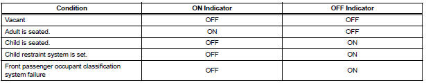
3. FUNCTION OF PASSENGER AIRBAG ON/OFF INDICATOR
- Initial check
- Turn the ignition switch to the ON position.
- The passenger airbag ON/OFF indicator ("ON" and "OFF") comes on for approximately 4 seconds, then goes off for approximately 2 seconds.
- Approximately 6 seconds after the ignition switch is turned to the ON position, the passenger airbag ON/OFF indicator will be ON/ OFF depending on the conditions listed below.
HINT:
- The passenger airbag ON/OFF indicator comes on based on the timing chart below in order to check the indicator light circuit.
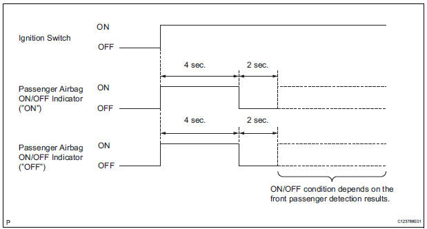
- When the Occupant Classification System has trouble, both the SRS warning light and the passenger airbag ON/OFF indicator ("OFF") come on. In this case, check the DTCs in the "Airbag System" first.
4. CHECK PASSENGER AIRBAG ON/OFF INDICATOR
- Turn the ignition switch to the ON position.
- Check that the passenger airbag ON/OFF indicator ("ON" and "OFF") comes on for approximately 4 seconds, then goes off for approximately 2 seconds.
HINT: Refer to the table in the previous step regarding the passenger airbag ON/OFF indicator when the ignition switch is turned to the ON position and approximately 6 seconds have elapsed.
 Terminals of ECU
1. OCCUPANT CLASSIFICATION ECU
...
 DTC check / clear
1. DTC CHECK
HINT:
When DTC B1150/23 is detected as a result of
troubleshooting for "Airbag System", perform
troubleshooting for the Occupant Classification System.
Check t ...
Other materials:
Short to GND in Front Passenger Side Squib
Circuit
DTC B0107/51 Short to GND in Front Passenger Side Squib
Circuit
DESCRIPTION
The front passenger side squib circuit consists of the center airbag sensor
assembly and the front
passenger airbag assembly.
The circuit instructs the SRS to deploy when deployment conditions are met.
DTC B0107/ ...
Removal
1. REMOVE BATTERY
2. REMOVE AIR CLEANER ASSEMBLY
HINT:
(See page EM-26)
3. REMOVE SPEED SENSOR (NT SENSOR)
(a) Disconnect the speed sensor connector.
(b) Remove the bolt and speed sensor.
4. REMOVE SPEED SENSOR (NC SENSOR)
(a) Disconnect the speed sensor connector.
(b) Remove th ...
Reassembly
1. INSTALL SEAT POSITION AIRBAG SENSOR (for Driver Seat)
2. INSTALL FRONT SEAT CUSHION SHIELD LOWER LH
Install the front seat cushion shield lower LH with
the screw.
3. INSTALL FRONT SEAT CUSHION SHIELD LOWER
RH
HINT:
Use the same procedures for the RH side and LH side.
4. INSTAL ...
