Toyota Sienna Service Manual: ECM / PCM Internal Engine Off Timer Performance
DTC P2610 ECM / PCM Internal Engine Off Timer Performance
DTC SUMMARY
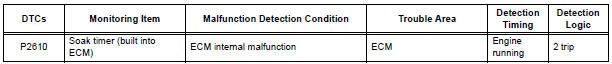
DESCRIPTION
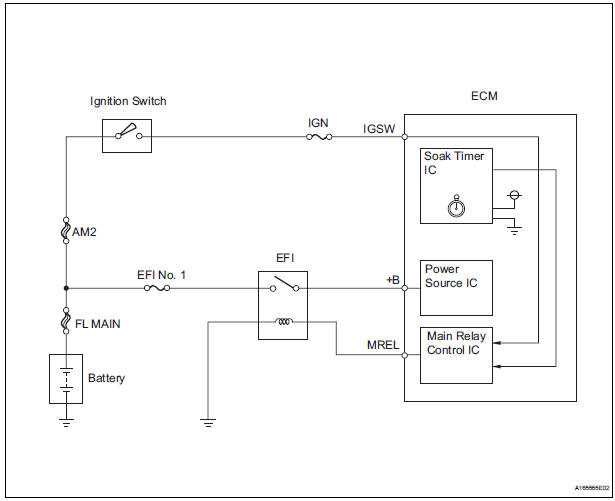
To ensure the accuracy of the EVAP (Evaporative Emission) monitor values, the soak timer, which is built into the ECM, measures 5 hours (+/- 15 minutes) from when the ignition switch is turned off, before the monitor is run. This allows the fuel to cool down, which stabilizes the Fuel Tank Pressure (FTP). When 5 hours have elapsed, the ECM turns on.
MONITOR DESCRIPTION
5 hours after the ignition switch is turned off, the soak timer activates the ECM to begin the EVAP system monitor. While the engine is running, the ECM monitors the synchronization of the soak timer and the CPU clock. If these two are not synchronized, the ECM interprets this as a malfunction, illuminates the MIL and sets the DTC (2 trip detection logic).
MONITOR STRATEGY
TYPICAL ENABLING CONDITIONS
TYPICAL MALFUNCTION THRESHOLDS
INSPECTION PROCEDURE
HINT:
- DTC P2610 is set if an internal ECM problem is detected.
Diagnostic procedures are not required.
ECM replacement is required.
- Read freeze frame data using the intelligent tester. The ECM records vehicle and driving condition information as freeze frame data the moment a DTC is stored. When troubleshooting, freeze frame data can be helpful in determining whether the vehicle was running or stopped, whether the engine was warmed up or not, whether the air-fuel ratio was lean or rich, as well as other data recorded at the time of a malfunction.
1 REPLACE ECM
- Replace the ECM
2 CHECK WHETHER DTC OUTPUT RECURS
- Connect the intelligent tester to the DLC3.
- Turn the ignition switch to the ON position.
- Clear the DTCs.
- Start the engine and wait for 10 minutes or more.
- Select the following menu items on the tester: DIAGNOSIS / ENHANCED OBD II / DTC INFO / PENDING CODES.
- If no pending DTC is displayed, the repair has been successfully completed.
OK: No DTC output
END
 Evaporative Emission System Switching Valve
Control Circuit High
Evaporative Emission System Switching Valve
Control Circuit High
DTC P2420 Evaporative Emission System Switching Valve
Control Circuit High
DTC SUMMARY
DESCRIPTION
The circuit description can be found in the EVAP (Evaporative Emission)
System.
INSPECTION ...
 A/F Sensor Circuit Slow Response
DTC P2A00 A/F Sensor Circuit Slow Response (Bank 1
Sensor 1)
DTC P2A03 A/F Sensor Circuit Slow Response (Bank 2
Sensor 1)
HINT:
DTC P2A00 indicates malfunctions related to the bank 1 A/F ...
Other materials:
When stopping the engine with the shift lever in a position other
than P
If the engine is stopped with the shift lever in a position other than P,
the engine switch will not be turned off but instead be turned to
ACCESSORY mode. Perform the following procedure to turn the
switch off:
Check that the parking brake is set.
Shift the shift lever to P.
Check that t ...
Short in Side Squib RH Circuit
DTC B0110/43 Short in Side Squib RH Circuit
DESCRIPTION
The side squib RH circuit consists of the center airbag sensor assembly and
the front seat side airbag
assembly RH.
The circuit instructs the SRS to deploy when deployment conditions are met.
DTC B0110/43 is recorded when a short cir ...
Installation
1. INSTALL FRONT SHOCK ABSORBER WITH COIL SPRING
(a) Install the front shock absorber with coil spring as
shown in the illustration.
(b) Install the 3 nuts to the upper side of the front shock
absorber with coil spring.
Torque: 80 N*m (816 kgf*cm, 59 ft.*lbf)
(c) Install the 2 bolt ...
