
Toyota Sienna Service Manual: Disassembly
1. REMOVE BACK DOOR GARNISH CENTER
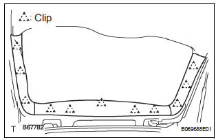
- Using a clip remover, disengage the 5 clips and remove the garnish center.
2. REMOVE BACK DOOR SIDE GARNISH LH
- Using a clip remover, disengage the 3 clips and remove the side garnish.
3. REMOVE BACK DOOR SIDE GARNISH RH
- Using a clip remover, disengage the 3 clips and remove the side garnish.
4. REMOVE BACK DOOR PULL STRAP
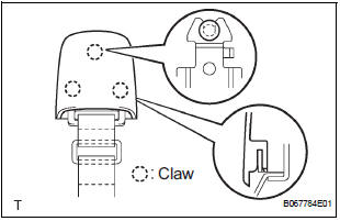
- Using a screwdriver, disengage the claws and
remove the strap cover.
HINT: Tape the screwdriver tip before use.
- Remove the bolt and strap.
5. REMOVE BACK DOOR TRIM BOARD ASSEMBLY
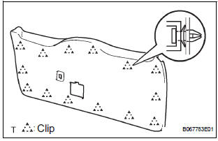
- Using the screwdriver, disengage the 14 clips and
remove the trim board.
HINT: Tape the screwdriver tip before use.
- Remove the service hole cover from the trim board.
6. REMOVE BACK-UP LIGHT ASSEMBLY LH (See page LI-90)
7. REMOVE BACK-UP LIGHT ASSEMBLY RH (See page LI-90)
8. REMOVE BACK DOOR GARNISH SUB-ASSEMBLY OUTSIDE (See page ET-39)
9. REMOVE BACK DOOR LOCK ASSEMBLY
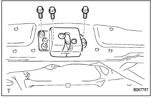
- Disconnect the connector.
- Remove the 3 bolts and lock.
10. REMOVE BACK DOOR BASE STOPPER BRACKET
- Remove the 4 bolts and 2 stopper brackets.
11. REMOVE BACK DOOR STOPPER LOWER
- Remove the 4 bolts and 2 stoppers.
12. REMOVE REAR SPOILER COVER (See page ET-18)
13. REMOVE BACK DOOR STAY SUB-ASSEMBLY LH
14. REMOVE BACK DOOR STAY SUB-ASSEMBLY RH
 Back door
COMPONENTS
...
 Adjustment
HINT:
On the RH side, use the same procedures as on the LH
side.
Since a centering bolt is used as door hinge mounting
bolts on the body side and the door side, the door cannot
be adjusted ...
Other materials:
Installation
1. INSTALL FRONT DRIVE SHAFT ASSEMBLY LH
(a) Coat the spline of the inboard joint shaft assembly
with ATF.
(b) Align the shaft splines and install the drive shaft
assembly with a brass bar and hammer.
NOTICE:
Set the snap ring with the opening side facing
down.
Be careful not to d ...
Initialization
NOTICE:
Resetting the power window motor (initializing the
pulse sensor) is necessary when the battery terminal
is disconnected; when the master switch, wire
harness, power window regulator and power window
motor are replaced or removed/installed; or when the
fuses are replaced. ...
Installation
1. INSTALL TIRE PRESSURE WARNING ECU
(a) Connect the connector to the tire pressure warning
ECU.
(b) Install the tire pressure warning ECU with the screw.
2. INSTALL INSTRUMENT PANEL SAFETY PAD SUBASSEMBLY
HINT:
Refer to the instructions for INSTALLATION of the
instrument panel safety ...
