Toyota Sienna Service Manual: Disassembly
1. REMOVE CYLINDER BOOT
(a) Using a screwdriver, remove the set ring and cylinder boot.
2. REMOVE REAR DISC BRAKE PISTON
(a) Place a shop rug, between the rear disc brake piston and the disc brake cylinder.
(b) Use compressed air to remove the rear disc brake piston from the disc brake cylinder.
| CAUTION: Do not place your fingers in front of the piston when using compressed air. |
NOTICE: Do not spatter the brake fluid.
3. REMOVE PISTON SEAL
(a) Using a screwdriver, remove the piston seal from the disc brake cylinder assembly rear LH.
NOTICE: Do not damage the inner cylinder and cylinder groove.
4. REMOVE REAR DISC BRAKE BLEEDER PLUG CAP
5. REMOVE REAR DISC BRAKE BLEEDER PLUG
(a) Remove the rear disc brake bleeder plug from the disc brake cylinder assembly rear LH.
6. REMOVE REAR DISC
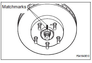
(a) Make matchmarks on the rear disc and the axle hub.
(b) Remove the rear disc.
 Removal
HINT:
Remove the RH side by the same procedure as the LH side.
1. REMOVE REAR WHEEL
2. DRAIN BRAKE FLUID
NOTICE:
Wash the brake fluid off immediately if it attaches to
any painted surface.
3. S ...
 Inspection
1. INSPECT BRAKE CYLINDER AND PISTON
(a) Check the brake cylinder bore and rear disc brake
piston for rust or scoring.
2. INSPECT PAD LINING THICKNESS
(a) Using a ruler, measure the pad lining ...
Other materials:
Passenger Airbag ON/OFF Indicator Circuit
Malfunction
DTC B1152/28 Passenger Airbag ON/OFF Indicator Circuit
Malfunction
DESCRIPTION
The passenger airbag ON/OFF indicator circuit consists of the center airbag
sensor assembly and
passenger airbag ON/OFF indicator.
This circuit indicates the operation condition of the front passenger airbag,
t ...
Inspection
1. INSPECT POWER STEERING RACK
(a) Using a dial indicator, check the power steering rack
for runout and for teeth wear and damage.
Maximum runout:
0.3 mm (0.012 in.)
If necessary, replace the rack & pinion power
steering gear assembly.
(b) Check the back surface for wear and damag ...
Terminals of ECU
1. CHECK DISTANCE CONTROL ECU
Reference: waveform 1
HINT:
Terminal: LRDD - SGND
Gauge set: 2 V/DIV., 10 ms./DIV.
Condition: ignition switch in the ON position
Reference: waveform 2
HINT:
Terminal: LRRD - SGND
Gauge set: 2 V/ ...
