Toyota Sienna Service Manual: Reassembly
1. INSTALL FRONT DRIVE SHAFT BEARING
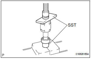
(a) Using SST and a press, install a new front drive shaft bearing.
SST 09710-30021 (09710-03141), 09527-10011
NOTICE: Bearing should be completely installed.
2. INSTALL FRONT DRIVE SHAFT RH HOLE SNAP RING
(a) Using a snap ring expander, install a new front drive shaft RH hole snap ring.
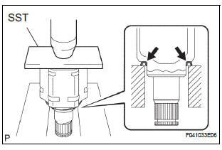
3. INSTALL FRONT DRIVE SHAFT DUST COVER
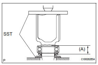
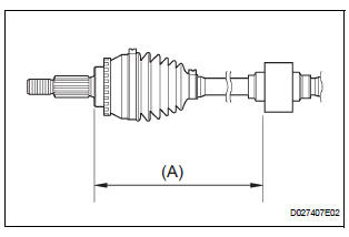
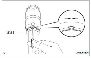
(a) Using SST and a press, install a new drive shaft dust cover until the distance from the tip of the center drive shaft to the drive shaft dust cover meets the specification, as shown in the illustration.
SST 09726-40010, 09527-10011 Distance (A): 26.8 to 27.4 mm (1.0551 to 1.0787 in.)
4. INSTALL FRONT DRIVE SHAFT DUST COVER RH (for 2WD)
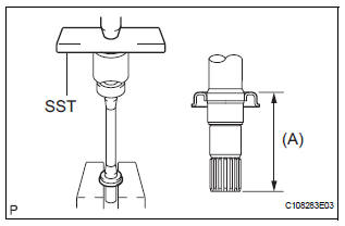
(a) Using SST and a press, install a new drive shaft dust cover RH until the distance from the tip of the center drive shaft to the drive shaft dust cover RH meets the specification, as shown in the illustration.
SST 09527-10011 Distance: 109.5 mm (4.311 in.)
NOTICE:
- Dust cover should be completely installed.
- Be careful not to damage the dust cover.
5. INSTALL FRONT DRIVE SHAFT DUST COVER RH (for 4WD)
(a) Using SST and a press, install a new drive shaft dust cover RH.
SST 09527-10011
NOTICE:
- Dust cover should be completely installed.
- Be careful not to damage the dust cover.
6. INSTALL FRONT DRIVE SHAFT DUST COVER LH
(a) Using SST and a press, install a new drive shaft dust cover LH.
SST 09527-10011
NOTICE:
- Dust cover should be completely installed.
- Be careful not to damage the dust cover.
7. INSTALL FRONT DRIVE SHAFT LH HOLE SNAP RING
(a) Install a new hole snap ring to the inboard joint shaft assembly.
8. INSTALL OUTBOARD JOINT BOOT
HINT: Before installing the boots, wrap the spline of the drive shaft with vinyl tape to prevent the boots from being damaged.
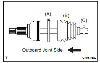
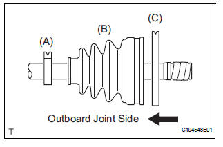
(a) Install new parts to the outboard joint shaft assembly in the following order.
(1) Outboard joint boot No. 2 clamp (A)
(2) Outboard joint boot (B)
(3) Outboard joint boot clamp (C)
(b) Pack the outboard joint shaft and boot with grease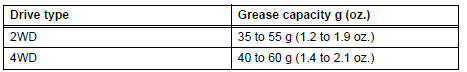
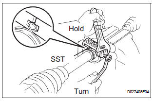
9. INSTALL OUTBOARD JOINT BOOT NO. 2 CLAMP
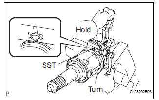
(a) Hold the outboard joint shaft assembly between aluminium plates in a vise.
NOTICE: Do not overtighten the vise.
(b) Install the outboard joint boot No. 2 clamp onto the boot.
(c) Place SST onto the outboard joint boot No. 2 clamp.
SST 09521-24010
(d) Tighten the SST so that the outboard joint boot No.
2 clamp is pinched.
SST 09521-24010
NOTICE: Do not overtighten the SST.
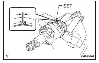
(e) Using SST, measure the clearance of the outboard joint boot No. 2 clamp.
SST 09240-00020 Clearance: 0.8 mm (0.031 in.) or less
NOTICE: When the measured value is greater than the specified value, retighten the clamp.
10. INSTALL OUTBOARD JOINT BOOT CLAMP
(a) Install the outboard joint boot clamp perform the same procedures as for the outboard joint boot No.
2 clamp.
11. INSTALL FRONT DRIVE SHAFT DAMPER
(a) Install the drive shaft damper to the drive shaft.
(b) Make sure that the damper is on the shaft groove.
(c) Set the distance, as specified below.
Distance: 221.0 +- 2.0 mm (8.701 +- 0.079 in.)
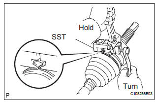
12. INSTALL FRONT DRIVE SHAFT DAMPER RH CLAMP
(a) Hold the outboard joint shaft assembly between aluminium plates in a vise.
NOTICE: Do not overtighten the vise.
(b) Install the drive shaft damper clamp to the damper.
NOTICE: Be sure to install the clamp in the correct position.
(c) Place SST onto the drive shaft damper clamp.
SST 09521-24010
(d) Tighten the SST so that the clamp is pinched.
SST 09521-24010
NOTICE: Do not overtighten the SST.
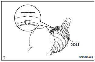
(e) Using SST, measure the clearance of the drive shaft damper clamp.
SST 09240-00020
Clearance: 0.8 mm (0.031 in.) or less
NOTICE: Using SST, measure the clearance of the drive shaft damper clamp.
13. INSTALL INBOARD JOINT ASSEMBLY
(a) Install new parts to the inboard joint shaft assembly in the following order.
(1) Inboard joint boot clamp (A) (2) Inboard joint boot (B) (3) Inboard joint boot No. 2 clamp (C)
(b) Hold the outboard joint shaft assembly between aluminium plates in a vise.
NOTICE: Do not overtighten the vise.
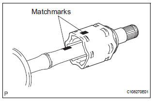
(c) Place the beveled side of the tripod axial spline toward the outboard joint shaft.
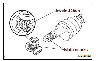
(d) Align the matchmarks.
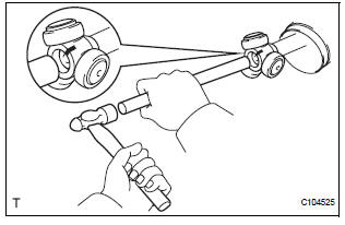
(e) Using a brass bar and hammer, tap in the tripod to the outboard joint shaft.
NOTICE:
- Do not tap the roller.
- Be sure to install the tripod in the correct direction.
(f) Using a snap ring expander, install a new front inner shaft snap ring.
(g) Pack the inboard joint shaft and boot with grease.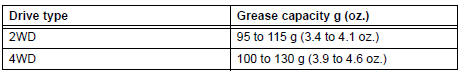
(h) Align the matchmarks, install the inboard joint assembly to the outboard joint shaft assembly.
14. INSTALL FR AXLE INBOARD JOINT BOOT
(a) Install the inboard joint boot to the inboard joint assembly.
15. INSTALL NO. 2 FRONT AXLE INBOARD JOINT BOOT LH CLAMP
(a) Hold the outboard joint shaft assembly between aluminium plates in a vise.
NOTICE: Do not overtighten the vise.
(b) Install the No. 2 front axle inboard joint boot LH clamp onto the boot.
(c) for Omega Type:
(1) Place SST onto the No. 2 front axle inboard joint boot LH clamp.
SST 09521-24010
(2) Tighten the SST so that the No. 2 front axle inboard joint boot LH clamp is pinched.
SST 09521-24010
NOTICE: Do not overtighten the SST.
(3) Using SST, measure the clearance of the No. 2 front axle inboard joint boot LH clamp.
SST 09240-00020 Clearance: 0.8 mm (0.031 in.) or less
NOTICE: When the measured value is greater than the specified value, retighten the clamp.
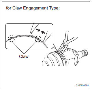
(d) for claw engagement type: (1) Using needle nose pliers, install the No. 2 front axle inboard joint boot clamp as shown in the illustration.
16. INSTALL FRONT AXLE INBOARD JOINT BOOT LH CLAMP
(a) Install the front axle inboard joint boot LH clamp perform the same procedures as for the No. 2 front axle inboard joint boot LH clamp.
17. INSPECT FRONT DRIVE SHAFT ASSEMBLY
(a) Check that there is no excessive play in the outboard joint.
(b) Check that the inboard joint slides smoothly in the thrust direction.
(c) Check that there is no excessive play in the radial directions of the inboard joint.
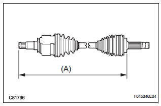
(d) Check the boots for damage.
HINT:
For dimension (A), refer to the following table.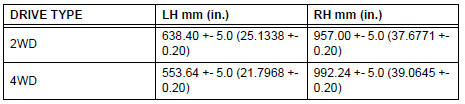
 Inspection
1. INSPECT FRONT DRIVE SHAFT ASSEMBLY LH
(a) Check that there is no remarkable play in the radial
direction of the outboard joint.
(b) Check that the inboard joint slides smoothly in the
thr ...
 Installation
1. INSTALL FRONT DRIVE SHAFT ASSEMBLY LH
(a) Coat the spline of the inboard joint shaft assembly
with ATF.
(b) Align the shaft splines and install the drive shaft
assembly with a brass bar a ...
Other materials:
Power steering
Sst
Recommended tools
EQUIPMENT
LUBRICANT
SSM
...
Removal
HINT:
On the RH side, use the same procedures as on the LH side.
1. REMOVE REAR NO. 1 SEAT ASSEMBLY LH
HINT:
Captain seat type:
Center seat type:
2. REMOVE REAR DOOR WEATHERSTRIP LH
3. REMOVE ROPE HOOK ASSEMBLY
4. REMOVE BACK DOOR SCUFF PLATE
5. REMOVE ROOF HEADLINING GA ...
If your vehicle has to
be stopped in an
emergency
Only in an emergency, such as if it becomes impossible to stop
the vehicle in the normal way, stop the vehicle using the following
procedure:
Steadily step on the brake pedal with both feet and firmly depress it.
Do not pump the brake pedal repeatedly as this will increase the effort
requi ...
