Toyota Sienna Service Manual: Disassembly
1. REMOVE RH SEAT REAR SEAT RECLINING COVER
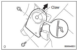
- Remove the 2 screws.
- Remove the RH seat rear seat reclining cover by pulling it out in the arrow mark direction shown in the illustration.
2. REMOVE LH SEAT REAR SEAT RECLINING COVER
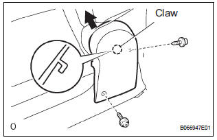
- Remove the 2 screws.
- Remove the LH seat rear seat reclining cover by pulling it out in the arrow mark direction shown in the illustration.
3. REMOVE REAR SEATBACK ASSEMBLY LH
- Disengage the reclining remote control cable.
- Disengage the rear seat lock release strap cable.
- Remove the 4 bolts and rear seatback assembly LH.
4. REMOVE REAR NO. 2 SEAT LAP BELT ASSEMBLY CENTER WITH INNER LH
- Remove the bolt and rear No. 2 seat lap belt assembly center with inner LH.
5. REMOVE NO. 2 REAR SEAT COVER BEZEL
- Remove the 5 screws and cover bezel.
6. REMOVE NO. 2 SEATBACK LOCK CONTROL BEZEL
- Remove the screw and No. 2 seatback lock control bezel.
7. REMOVE NO. 2 SEATBACK COVER LH
- Disengage the claw and remove the 4 headrest supports.
- Remove the hog rings and seatback cover together with the pad.
- Remove the hog rings and No. 2 seatback cover LH.
8. REMOVE REAR SEAT LOCK RELEASE STRAP ASSEMBLY
- Remove the nut and rear seat lock release strap assembly.
9. REMOVE REAR SEATBACK CONNECTING LH WIRE
- Remove the screw and rear seatback connecting LH wire.
10. REMOVE RECLINING RELEASE HANDLE SUBASSEMBLY LH
- Remove the nut and reclining release handle subassembly LH.
11. REMOVE NO. 2 RECLINING ADJUSTER RELEASE HANDLE LH
- Remove the nut and No. 2 reclining adjuster release handle LH.
12. REMOVE REAR SEAT INNER BELT ASSEMBLY LH
- Remove the bolt and rear seat inner belt assembly LH.
13. REMOVE REAR NO. 2 SEAT INNER BELT ASSEMBLY LH
- Remove the bolt and rear No. 2 seat inner belt assembly LH.
14. REMOVE NO. 2 SEAT CUSHION COVER SUBASSEMBLY LH
- Remove the hog rings and cushion cover together with the pad.
- Remove the hog rings and No. 2 seat cushion cover sub-assembly LH.
15. REMOVE LOCUS CABLE LH
- Remove the nut and locus cable LH.
16. REMOVE NO. 2 SEAT CUSHION SPRING ASSEMBLY LH
17. REMOVE REAR SEAT STAY SUB-ASSEMBLY
- Remove the nut and rear seat stay sub-assembly.
 Removal
1. REMOVE REAR SEAT LEG SIDE GARNISH SUBASSEMBLY LH
Disengage the clips and remove the seat leg side
garnish.
2. REMOVE REAR NO. 2 SEAT ASSEMBLY LH
Remove the bolt and locus cab ...
 Reassembly
1. INSTALL REAR SEAT STAY SUB-ASSEMBLY
Install the rear seat stay sub-assembly with the nut.
Torque: 5.5 N*m (56 kgf*cm, 49 in.*lbf)
2. INSTALL NO. 2 SEAT CUSHION SPRING ASSEMBLY
LH
3 ...
Other materials:
Removal
1. REMOVE WINDSHIELD WIPER MOTOR ASSEMBLY
2. REMOVE FRONT OUTER COWL TOP PANEL SUBASSEMBLY
3. DRAIN ENGINE COOLANT
4. REMOVE V-BANK COVER SUB-ASSEMBLY
5. REMOVE NO. 2 AIR CLEANER INLET
6. REMOVE NO. 1 AIR CLEANER INLET
7. REMOVE AIR CLEANER CAP SUB-ASSEMBLY
Disconnect the 3 vacuum hoses.
...
Data list
HINT:
Reading the DATA LIST displayed on an intelligent tester
enables values, including those of the switches, sensors,
and actuators, to be checked without removing any
parts. Reading the DATA LIST as the first step in
troubleshooting is one method to shorten diagnostic
time.
NOTICE: ...
Removal
HINT:
Use the same procedures for the RH side and LH side.
The procedures listed below are for the LH side.
1. PRECAUTION
CAUTION: Be sure to read "PRECAUTION" thoroughly before
servicing.
2. DISCONNECT CABLE FROM NEGATIVE BATTERY
TERMINAL
NOTICE:
Wait for 90 seconds ...
