Toyota Sienna Service Manual: Removal
1. REMOVE V-BANK COVER SUB-ASSEMBLY (See page EM-28) 2. REMOVE NO. 1 ENGINE UNDER COVER (See page EM-26) 3. DRAIN ENGINE COOLANT (See page CO-6) 4. REMOVE NO. 2 AIR CLEANER INLET (See page EM- 28) 5. REMOVE BATTERY (See page EM-26) 6. REMOVE FRONT BUMPER ASSEMBLY (See page ET-3) 7. REMOVE FRONT BUMPER ENERGY ABSORBER 8. REMOVE NO. 1 AIR CLEANER INLET (See page EM- 28) 9. DISCONNECT RADIATOR RESERVE TANK HOSE OR PIPE
(a) Disconnect the radiator reserve tank hose or pipe from the radiator.
10. DISCONNECT NO. 1 RADIATOR HOSE
(a) Disconnect both connections of the No. 1 radiator hose from the radiator.
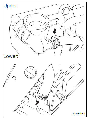
11. DISCONNECT NO. 2 RADIATOR HOSE
(a) Disconnect the No. 2 radiator hose from the radiator.
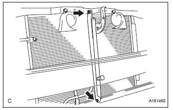
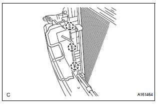
12. REMOVE HOOD LOCK RELEASE LEVER PROTECTOR
(a) Disengage the 4 claws and remove the hood lock release lever protector.
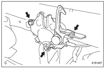
(b) Remove the 3 bolts.
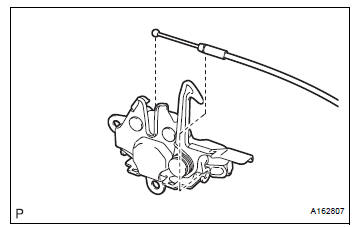
(c) Disconnect the cable and remove the hood lock assembly.
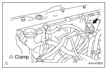
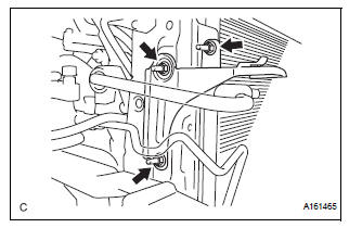
14. REMOVE HOOD LOCK SUPPORT SUB-ASSEMBLY
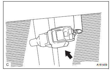
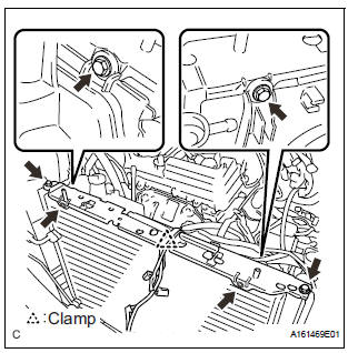
(a) Disconnect the ambient temperature sensor connector.
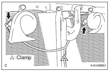
(b) Detach the clamp.
(c) Disconnect the low pitched horn and high pitched horn connectors.
(d) Remove the 2 bolts and hood lock support subassembly.
15. DISCONNECT COOLING FAN ECU CONNECTOR
(a) Disconnect the cooling fan ECU connector.
(b) Detach the clamp.
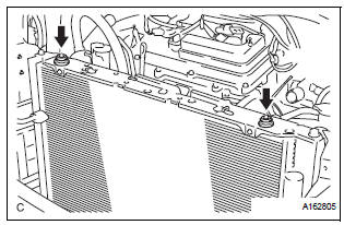
16. REMOVE RADIATOR UPPER SUPPORT SUBASSEMBLY
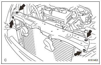
(a) Remove the 4 bolts and radiator upper support subassembly.
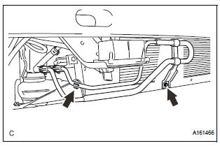
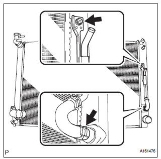
17. DISCONNECT NO. 2 OIL COOLER OUTLET TUBE SUB-ASSEMBLY
(a) Disconnect the No. 1 oil cooler inlet and No. 1 oil cooler outlet hoses from the No. 2 oil cooler outlet tube sub-assembly.
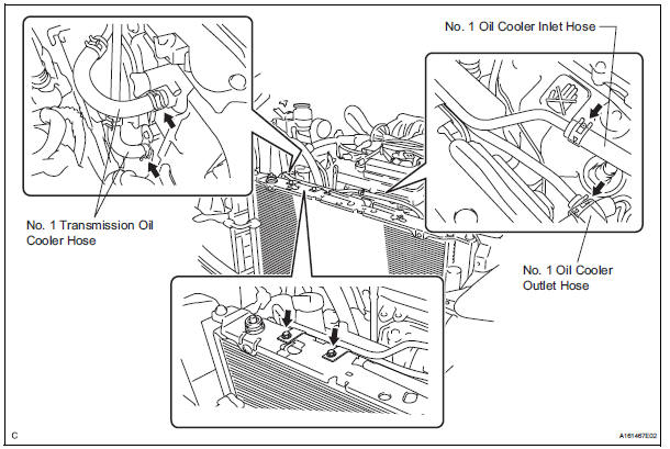
(b) Disconnect the No. 1 transmission oil cooler hoses from the radiator.
(c) Remove the 2 bolts and No. 2 oil cooler outlet tube sub-assembly.
18. REMOVE HEADLIGHT ASSEMBLY RH
(a) Use the same procedures for the RH side and LH side
HINT: See page LI-69
19. REMOVE RADIATOR SIDE DEFLECTOR RH
(a) Disengage the 3 claws and remove the radiator side deflector RH.
20. REMOVE HEADLIGHT BRACKET RH
(a) Remove the 3 nuts and headlight bracket RH.
21. REMOVE PRESSURE FEED TUBE ASSEMBLY
(a) Remove the 2 bolts.
22. REMOVE RADIATOR SUPPORT CUSHION
(a) Remove the 2 radiator support cushions from the No. 1 radiator support.
23. REMOVE NO.1 RADIATOR SUPPORT
(a) Detach the clamp.
(b) Remove the 6 bolts and No. 1 radiator support.
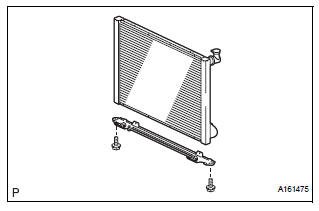
24. REMOVE RADIATOR ASSEMBLY WITH FAN SHROUD AND FAN MOTOR
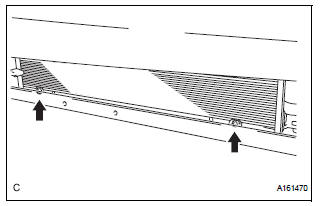
(a) Remove the 2 bolts and separate the condenser assembly from the radiator assembly with fan shroud and fan motor.
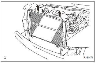
(b) Remove the radiator assembly with fan shroud and fan motor from the body.
25. REMOVE FAN SHROUD WITH FAN MOTOR
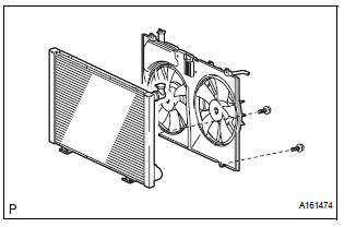
(a) Remove the 2 bolts and fan shroud with fan motor from the radiator.
26. REMOVE RADIATOR SUPPORT LOWER
(a) Remove the 2 radiator support lowers from the radiator assembly.
27. REMOVE NO. 2 RADIATOR SUPPORT
(a) Remove the 2 bolts and No. 2 radiator support from the radiator.
28. DISCONNECT INLET SUB-ASSEMBLY
(a) Disconnect the inlet hose from the radiator.
(b) Remove the bolt and inlet sub-assembly from the radiator.
 On-vehicle cleaning
1. INSPECT RADIATOR ASSEMBLY
(a) Check that the radiator and condenser are not
blocked with leaves, dirt, or insects. Clean the hose
connections.
If the fins are blocked, wash them with water or ...
 Disassembly
1. REMOVE RADIATOR WATER INLET
(a) Remove the 2 bolts and radiator water inlet.
2. REMOVE DRAIN PLUG
(a) Remove the drain plug and air drain plug.
(b) Remove the 2 O-rings.
3. REMOVE LOWER ...
Other materials:
Turning the high beam on/off manually
Switching to low beam
Pull the lever to the original
position.
Switching to high beam
Turn the light switch to the
position.
The Automatic High Beam can be operated when
The engine switch is in the “ON” position (vehicles without a smart key
system)
or IGNITION ON mode (vehicl ...
Problem symptoms table
HINT:
Before inspecting the suspected areas listed in the table
below, check the fuse and relay.
Before inspecting the suspected areas listed in the table
below, check for DTCs.
Methods used to verify the cause of the problem are listed
in order of probability in the ...
Open in Pump Motor Circuit
DTC C1251/51 Open in Pump Motor Circuit
DESCRIPTION
WIRING DIAGRAM
INSPECTION PROCEDURE
1 PERFORM ACTIVE TEST USING INTELLIGENT TESTER (ABS MOTOR RELAY)
(a) Connect the intelligent tester to the DLC3.
(b) Start the engine.
(c) Select the ACTIVE TEST mode on the intelligent tester.
...
