Toyota Sienna Service Manual: Engine coolant temperature sensor
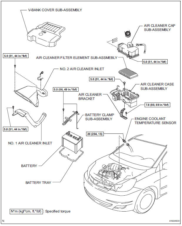
COMPONENTS
REMOVAL
1. DRAIN ENGINE COOLANT (See page CO-6) 2. REMOVE V-BANK COVER SUB-ASSEMBLY (See page EM-28) 3. REMOVE NO. 2 AIR CLEANER INLET (See page EM- 28) 4. REMOVE NO. 1 AIR CLEANER INLET (See page EM- 28) 5. REMOVE AIR CLEANER CAP SUB-ASSEMBLY (See page ES-493) 6. REMOVE AIR CLEANER CASE SUB-ASSEMBLY (See page EM-28) 7. REMOVE ENGINE COOLANT TEMPERATURE SENSOR
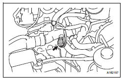
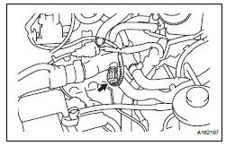
(a) Remove the engine coolant temperature sensor connector.
(b) Remove the engine coolant temperature sensor.
INSPECTION
1. INSPECT ENGINE COOLANT TEMPERATURE SENSOR
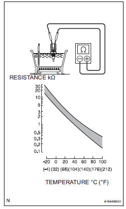
(a) Using an ohmmeter, measure the resistance between the terminals.
Standard resistance 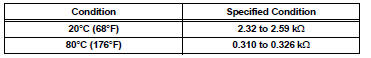
- If the result is as specified, do not replace the engine coolant temperature sensor
- If the result is not as specified, replace the engine coolant temperature sensor.
| NOTICE: In case of checking the engine coolant temperature sensor in water, do not allow water to go into the terminals. After checking, dry the engine coolant temperature sensor. |
INSTALLATION
1. INSTALL ENGINE COOLANT TEMPERATURE SENSOR
(a) Install the engine coolant temperature sensor.
Torque: 20 N*m (204 kgf*cm, 15 ft.*lbf) (b) Connect the engine coolant temperature sensor connector.
2. INSTALL AIR CLEANER CASE SUB-ASSEMBLY (See page EM-59) 3. INSTALL AIR CLEANER CAP SUB-ASSEMBLY (See page ES-496) 4. INSTALL NO. 1 AIR CLEANER INLET (See page EM- 59) 5. INSTALL NO. 2 AIR CLEANER INLET (See page EM- 60) 6. ADD ENGINE COOLANT (See page CO-7) 7. INSPECT FOR ENGINE COOLANT LEAK (See page CO-1) 8. INSTALL V-BANK COVER SUB-ASSEMBLY (See page EM-63)
 Crankshaft position sensor
Components
Removal
1. Remove compressor and magnetic clutch
HINT:
(See page AC-227 )
2. REMOVE CRANKSHAFT POSITION SENSOR
(a) Disconnect the crankshaft position sensor
connector.
(b) R ...
 Knock sensor
COMPONENTS
REMOVAL
1. DISCHARGE FUEL SYSTEM PRESSURE
(See page FU-13)
2. REMOVE V-BANK COVER SUB-ASSEMBLY (See
page EM-28)
3. DRAIN ENGINE COOLANT (See page CO-6)
4. REMOVE WINDSHIE ...
Other materials:
Installation
1. INSTALL REAR DRIVE SHAFT ASSEMBLY LH
(a) Install the drive shaft to the axle carrier.
NOTICE:
Be careful not to damage the boot and ABS
speed sensor rotor to the drive shaft and oil seal
of the axle hub bearing.
(b) Align the matchmarks and connect the drive shaft to
the side gear shaf ...
Towing with a wheel-lift type truck
From the front (2WD models)
Release the parking brake.
From the front (AWD models)
Use a towing dolly under the rear
wheels.
From the rear
Use a towing dolly under the front
wheels. ...
Installation
1. INSTALL CHARCOAL CANISTER ASSEMBLY
(a) Install the 3 bolts and charcoal canister.
Torque: 29 N*m (296 kgf*cm, 21 ft.*lbf)
(b) Connect the purge line hose to the charcoal
canister.
(c) Connect the wire harness clamp.
(d) Connect the vapor pressure sensor connector.
(e) Connect t ...
