Toyota Sienna Service Manual: GPS Mark is not Displayed
INSPECTION PROCEDURE
1 CHECK CABIN
- Check the cabin for any object that might interrupt radio reception on the instrument panel. If such an object exists, remove it and check if the GPS mark reappears.
HINT: The GPS uses extremely faint radio waves originating from satellites. If the signal is interrupted by obstructions or other radio waves, the GPS may not be able to properly receive the signal.
OK: Mark appears
NORMAL OPERATION
2 CHECK SURROUNDINGS
- Check if the vehicle is in a location where GPS signal reception is poor. If the vehicle is in such a place, relocate the vehicle and check if the GPS mark reappears.
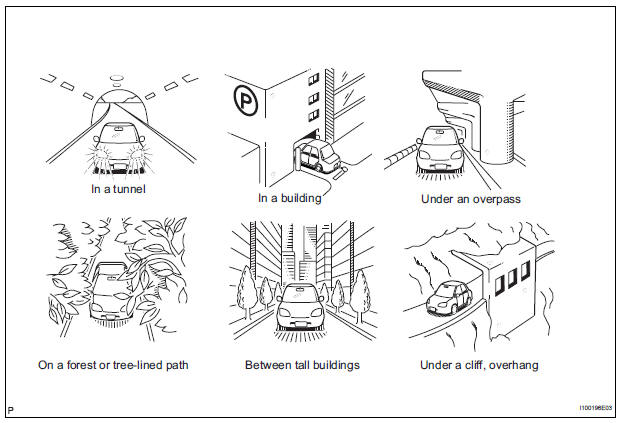
HINT: The GPS uses 24 satellites in 6 orbits. At any point in time, 4 satellites should be able to pinpoint your vehicle.
However, GPS signals may not reach the vehicle due to influence from the surroundings, vehicle direction, and time. For illustrated examples, see below.
OK: GPS mark is displayed.
SYSTEM RETURNS TO NORMAL
3 CHECK GPS INFORMATION (NAVIGATION CHECK MODE)
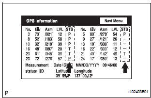
- Enter the "Navigation Check" mode (GPS Information).
- Check how many of the following codes appear in the "STS" column.
For DENSO Made:
T, P
For AISIN AW Made:
08H, 04H
OK: At least 3 codes appear
REPLACE RADIO AND NAVIGATION ASSEMBLY
 Current Position Display does not Appear
INSPECTION PROCEDURE
1 CHECK RADIO AND NAVIGATION ASSEMBLY
Check if a map disc is inserted into the map disc slot.
OK:
A map disc is inserted
2 CHECK MAP DISC
Check that the map ...
 Voice Guidance does not Function
INSPECTION PROCEDURE
1 CHECK NAVIGATION SYSTEM SETTING
Enter the "Menu" screen by pressing the "MENU" switch.
Select "Volume".
Check that " ...
Other materials:
Reassembly
1. INSTALL INPUT SHAFT OIL SEAL RING
(a) Compress a new input shaft oil seal ring from both
sides to reduce dimension A.
Dimension A:
5 mm (0.197 in.)
(b) Coat the oil seal ring with ATF and install it to the
input shaft.
NOTICE:
Do not expand the end gap of the oil seal ring
too much. ...
DTC check / clear
1. DTC CHECK/CLEAR (USING INTELLIGENT TESTER:)
DTC check
Connect the intelligent tester to the DLC3.
Turn the ignition switch to the ON position.
Read the DTCs on the tester screen.
DTC clear
Connect the intelligent tester to the DLC3.
&n ...
How to proceed with
troubleshooting
HINT:
Use the following procedures to troubleshoot the dynamic
laser cruise control system.
*: Use the intelligent tester
1 VEHICLE BROUGHT TO WORKSHOP
2 CUSTOMER PROBLEM ANALYSIS
3 PROBLEM SYMPTOM CONFIRMATION
Result
SYMPTOM SIMULATION
4 INSPECT BATTERY VOLTAGE
Stan ...
