Toyota Sienna Service Manual: Laser Sensor Power Source Circuit
DESCRIPTION
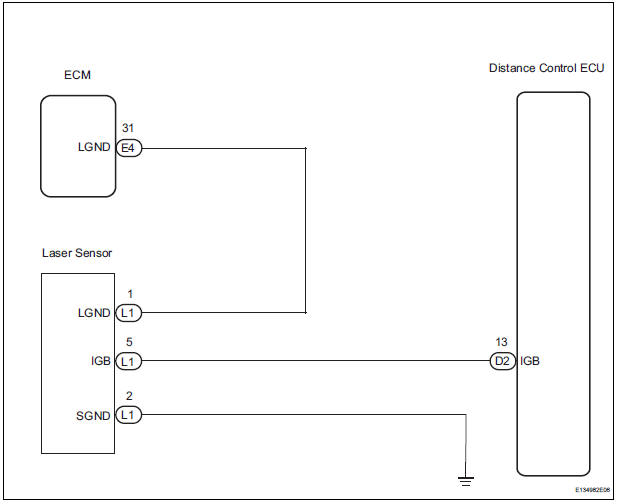
This circuit provides power to the laser sensor. The laser sensor emits radio waves towards an object in front and measures the distance and direction of the object by receiving the beam reflections. Based on the reflections, the sensor calculates the difference in speed between the vehicle and the object in front.
This data is transmitted to the distance control ECU. The ECM recognizes the laser sensor via terminals LGND. If an open circuit occurs in the wire harness between terminals LGND, the ECM cannot recognize the laser sensor. The ECM will stop the control of the vehicle-to-vehicle distance control mode and only the constant speed control mode can be used.
WIRING DIAGRAM
INSPECTION PROCEDURE
1 CHECK DISTANCE CONTROL ECU (IGB VOLTAGE)
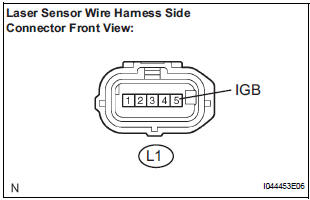
- Disconnect the L1 laser sensor connector.
- Measure the voltage according to the value(s) in the table below.
Standard voltage
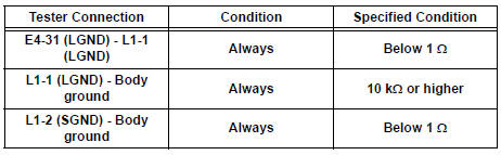
2 CHECK HARNESS AND CONNECTOR (LASER SENSOR - ECM AND BODY GROUND)
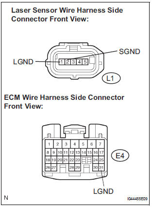
- Disconnect the E4 connector from the ECM.
- Measure the resistance according to the value(s) in the table below.
Standard resistance
PROCEED TO NEXT CIRCUIT INSPECTION SHOWN IN PROBLEM SYMPTOMS TABLE
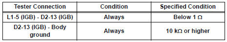
3 CHECK HARNESS AND CONNECTOR (LASER SENSOR - DISTANCE CONTROL ECU)
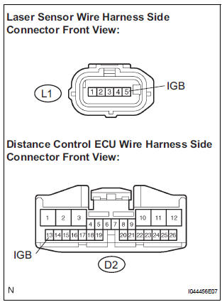
- Disconnect the D2 distance control ECU connector.
- Measure the resistance according to the value(s) in the table below.
Standard resistance
REPLACE DISTANCE CONTROL ECU
 Distance Control Switch Circuit
DESCRIPTION
The distance control switch sets the vehicle-to-vehicle distance mode. The
distance control switch is
installed in the steering pad switch. The vehicle-to-vehicle distance set value
...
 Wiper Signal Circuit
DESCRIPTION
The distance control ECU detects wiper operation. If the windshield wipers
operate in the HI or LO mode,
the cruise control is canceled and the warning sound "pong" is emitte ...
Other materials:
Safety Connect services
Automatic Collision Notification
In case of either airbag deployment or severe rear-end collision, the
system is designed to automatically call the response center. The
responding agent receives the vehicle’s location and attempts to
speak with the vehicle occupants to assess the level of emer ...
Initialization procedure
(a) Make sure that the ignition switch is off.
(b) Connect the intelligent tester to the DLC3.
(c) Turn the ignition switch to the ON position.
(d) Select "TIREPRESS" by following the prompts
displayed on the intelligent tester.
(e) Press the tire pressure warning reset sw ...
Glossary of sae and Toyota terms
This glossary lists all SAE-J1930 terms and abbreviations
used in this manual in compliance with SAE
recommendations, as well as their TOYOTA equivalents.
...
