Toyota Sienna Service Manual: Mass air flow meter
COMPONENTS
ON-VEHICLE INSPECTION
1. INSPECT MASS AIR FLOW METER
NOTICE:
|
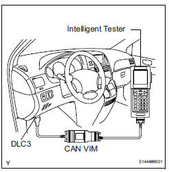
(a) Read the values using the intelligent tester (MAF).
NOTICE:
|
(1) Turn the ignition switch to the ON position (do not start the engine).
(2) Turn the tester on.
(3) Select the following menu items: DIAGNOSIS / ENHANCED OBD II / DATA LIST / PRIMARY / PRIMARY / MAF.
(4) Wait 30 seconds, and read the values on the intelligent tester.
Standard condition: Less than 0.70 g/s
- If the result is not as specified, replace the MAF meter.
- If the result is within the specified range, inspect the cause of the extremely rich or lean air fuel ratio.
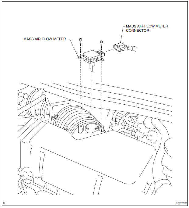
REMOVAL
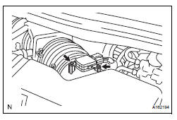
1. REMOVE MASS AIR FLOW METER
(a) Disconnect the mass air flow meter connector.
(b) Remove the 2 screws and mass air flow meter.
INSPECTION
1. INSPECT MASS AIR FLOW METER
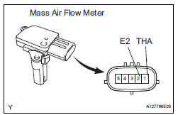
(a) Visually check for any foreign matter on the platinum hot wire (heater) of the mass air flow meter.
OK: There is no foreign matter.
If the result is not as specified, replace the mass air flow meter.
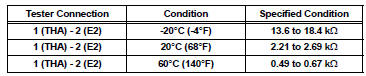
(b) Measure the resistance according to the value(s) in the table below.
Standard resistance
INSTALLATION
1. REMOVE MASS AIR FLOW METER
(a) Install the mass air flow meter with the 2 screws.
(b) Connect the mass air flow meter connector.
 Accelerator pedal rod
COMPONENTS
ON-VEHICLE INSPECTION
1. CHECK ACCELERATOR PEDAL ROD
(a) Check the voltage.
(1) Connect the intelligent tester to the DLC3.
(2) Turn the ignition switch to the ON position.
...
 Vvt sensor
COMPONENTS
ON-VEHICLE INSPECTION
1. CHECK VVT SENSOR OUTPUT VOLTAGE
(a) Turn the ignition switch to the ON position.
(b) Check the voltage between the specified terminal
and body grou ...
Other materials:
Short in Front Pretensioner Squib RH Circuit
DTC B0130/63 Short in Front Pretensioner Squib RH Circuit
DESCRIPTION
The front pretensioner squib RH circuit consists of the center airbag sensor
assembly and the front seat
outer belt assembly RH.
This circuit instructs the SRS to deploy when deployment conditions are met.
DTC B0130/63 ...
When towing full-time 4wd vehicles
Use one of the methods shown below to tow the
vehicle.
If the vehicle has trouble with the chassis or drive
train, use method 1 (flat bed truck).
WHEN TOWING FULL-TIME 4WD VEHICLES
NOTICE: Do not use any towing method other than those shown above.
The towing methods shown b ...
Capacity and distribution
Cargo capacity depends on the total weight of the occupants.
(Cargo capacity) = (Total load capacity) - (Total weight of occupants)
Steps for Determining Correct Load Limit
Locate the statement “The combined weight of occupants and
cargo should never exceed XXX kg or XXX lbs.” on your ...
