Toyota Sienna Service Manual: Dtc check / clear
1. DTC CHECK/CLEAR (WHEN USING SST CHECK WIRE):
(a) DTC check
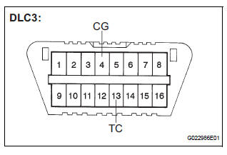
(1) Using SST, connect terminals TC and CG of the DLC3.
SST 09843-18040
(2) Turn the ignition switch to the ON position.
(3) Read the DTCs from the ABS warning light on the combination meter.
HINT:
If no code appears, inspect the TC and CG
terminal circuit and the ABS warning light circuit.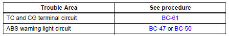
(4) As an example, refer to the chart below for the blinking patterns of the normal system code and trouble codes 11 and 21.
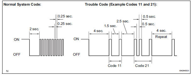
(5) The codes are explained in the code table (See page BC-14).
(6) After completing the check, disconnect terminals TC and CG of the DLC3, and turn off the display.
If 2 or more DTCs are detected at the same time, the DTCs will be displayed in ascending order.
(b) DTC clear
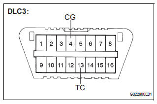
(1) Using SST, connect terminals TC and CG of the DLC3.
SST 09843-18040 (2) Turn the ignition switch to the ON position.
3) Clear the DTCs stored in the ECU by depressing the brake pedal 8 times or more within 5 seconds.
(4) Check that the warning light indicates the normal system code.
(5) Remove the SST from the terminals of the DLC3.
HINT: Clearing the DTCs cannot be performed by removing the battery cable.
2. DTC CHECK/CLEAR (WHEN USING INTELLIGENT TESTER):
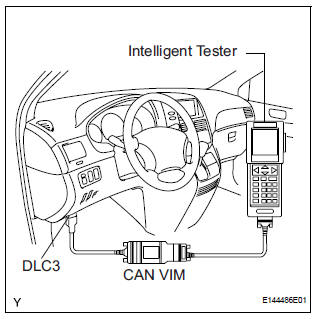
(a) DTC check
(1) Connect the intelligent tester to the DLC3.
(2) Turn the ignition switch to the ON position.
(3) Read the DTCs by following the prompts on the tester screen.
(b) DTC clear
(1) Connect the intelligent tester to the DLC3.
(2) Turn the ignition switch to the ON position.
(3) Operate the intelligent tester to clear the codes.
HINT: Refer to the intelligent tester operator's manual for further details.
3. END OF DTC CHECK/CLEAR
(a) Turn the ignition switch to the ON position.
(b) Check that the ABS warning light goes off within approximately 3 seconds.
 Diagnosis system
1. DESCRIPTION
(a) Release the parking brake pedal.
(b) Check the warning lights.
When ignition switch is turned ON, check that the
ABS warning light and brake warning light come on
for 3 ...
 Freeze frame data
1. FREEZE FRAME DATA
(a) Whenever a DTC is detected or the ABS operates,
the skid control ECU stores the current vehicle
(sensor) state as freeze frame data.
The skid control ECU stores the numb ...
Other materials:
Checking monitor status
The purpose of the monitor result (mode 06) is to allow
access to the results for on-board diagnostic monitoring tests
of specific components/systems that are not continuously
monitored. Examples are catalyst, evaporative emission
(EVAP) and thermostat.
The monitor result allows the OBD II sc ...
DTC check / clear
1. CHECK DTC (USING INTELLIGENT TESTER)
Checking DTCs.
Connect the intelligent tester to the DLC3.
Turn the ignition switch ON.
Read DTCs by following the prompts on the
tester screen.
HINT:
Refer to the intelligent tester operator's manual
for further deta ...
Stuck in Deceleration Sensor
DESCRIPTION
The yaw rate sensor and deceleration sensor signal is sent to the skid
control ECU through the CAN
communication system. When there is a malfunction in the communication, it will
be detected by the
diagnosis function.
WIRING DIAGRAM
INSPECTION PROCEDURE
HINT:
When ...
