
Toyota Sienna Service Manual: Anti-lock brake system
Parts location
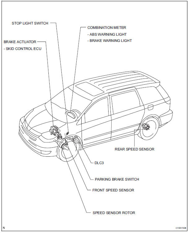
- How to proceed with troubleshooting
- Test mode procedure
- Problem symptoms table
- Diagnosis system
- Dtc check / clear
- Freeze frame data
- Data list / active test
- Diagnostic trouble code chart
 Brake control
...
 How to proceed with troubleshooting
The intelligent tester can be used at steps 3, 7, 10, and 13.
1 VEHICLE BROUGHT TO WORKSHOP
2 CUSTOMER PROBLEM ANALYSIS
(a) Interview the customer to confirm the trouble.
3 DTC CHECK/CLEAR AND ...
Other materials:
Installation
1. INSTALL FRONT DRIVE SHAFT ASSEMBLY LH
(a) Coat the spline of the inboard joint shaft assembly
with ATF.
(b) Align the shaft splines and install the drive shaft
assembly with a brass bar and hammer.
NOTICE:
Set the snap ring with the opening side facing
down.
Be careful not to d ...
Removal
HINT:
Use the same procedures for the RH side and LH side.
The procedures listed below are for the LH side.
1. PRECAUTION
CAUTION:
Be sure to read "PRECAUTION" thoroughly before
servicing.
2. DISCONNECT CABLE FROM NEGATIVE BATTERY
TERMINAL
NOTICE:
Wait for 90 se ...
TC and CG Terminal Circuit
DESCRIPTION
Connecting terminals TC and CG of the DLC3 causes the ECU to display the DTC
by blinking the ABS
warning light and/or VSC warning light.
WIRING DIAGRAM
INSPECTION PROCEDURE
NOTICE:
When replacing the brake actuator assembly, perform zero point calibration
(See page BC-70).
...
