Toyota Sienna Service Manual: ECU Power Source Circuit
DESCRIPTION
This is the power source for the tire pressure warning ECU.
WIRING DIAGRAM
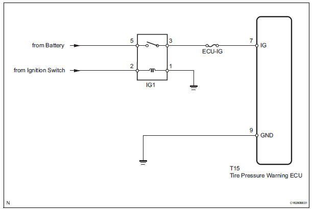
INSPECTION PROCEDURE
NOTICE: When replacing the tire pressure warning ECU, read the transmitter IDs stored in the old ECU using the intelligent tester and write them down before removal.
It is necessary to register an ID code after replacing the tire pressure warning valve and transmitter and/or the tire pressure warning ECU (See page TW-20).
1 INSPECT FUSE (ECU-IG)
(a) Remove the ECU-IG fuse from the instrument panel junction block.
(b) Measure the resistance of the fuse.
Standard resistance: Below 1 Ω


2 INSPECT IGNITION RELAY NO. 1
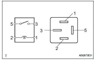
(a) Remove the IG1 relay from the instrument panel junction block.
(b) Measure the resistance according to the value(s) in the table below.
Standard resistance 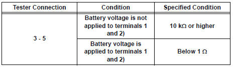


3 CHECK HARNESS AND CONNECTOR (ECU - BATTERY AND BODY GROUND)
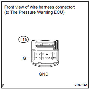
(a) Disconnect the T15 ECU connector.
(b) Measure the voltage according to the value(s) in the table below.
Standard voltage 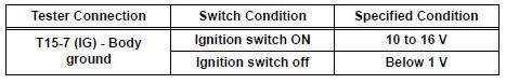
(c) Measure the resistance according to the value(s) in the table below.
Standard resistance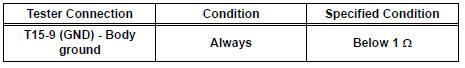


PROCEED TO NEXT CIRCUIT INSPECTION SHOWN IN PROBLEM SYMPTOMS TABLE (See page TW-28)
 Tire Pressure Warning Light Circuit
DESCRIPTION
If the ECU detects trouble, the tire pressure warning light blinks (comes on
after blinking for 1 minute) and
tire pressure monitor is cancelled at the same time. At this time, the ECU ...
 TC and CG Terminal Circuit
DESCRIPTION
DTC output mode is set by connecting terminals 13 (TC) and 4 (CG) of the
DLC3. The DTCs are indicated
by blinks of the tire pressure warning light.
WIRING DIAGRAM
HINT:
When eac ...
Other materials:
Pressure Control Solenoid "B" Performance (Shift
Solenoid Valve SL2)
SYSTEM DESCRIPTION
The ECM uses signals from the vehicle speed sensor to detect the actual gear
position (1st, 2nd, 3rd, 4th
or 5th gear).
Then the ECM compares the actual gear with the shift schedule in the ECM memory
to detect mechanical
problems of the shift solenoid valves, valve b ...
Absence of Registration Unit/ No Response for Connection Check/ Last Mode
Error/ No Response Against ON / OFF Command/ Mode Status Error/ Slave Reset
DTC 01-D5 Absence of Registration Unit
DTC 01-D8 No Response for Connection Check
DTC 01-D9 Last Mode Error
DTC 01-DA No Response Against ON / OFF Command
DTC 01-DB Mode Status Error
DTC 01-DE Slave Reset
DESCRIPTION
HINT:
*1: Even if no fault is present, this trouble code may b ...
Installation
1. INSTALL BRAKE PEDAL SUPPORT ASSEMBLY
(a) Install the brake pedal support sub-assembly with
the 4 nuts.
Torque: 16 N*m (160 kgf*cm, 12 ft.*lbf)
(b) Install the clip and clevis pin to the brake pedal
lever.
(c) Using needle-nose pliers, install the tension spring.
(d) Install the ...
