Toyota Sienna Service Manual: Tire Pressure Warning Light Circuit
DESCRIPTION
If the ECU detects trouble, the tire pressure warning light blinks (comes on after blinking for 1 minute) and tire pressure monitor is cancelled at the same time. At this time, the ECU records a DTC in the memory.
Connect terminals TC and CG of DLC3 to make the tire pressure warning light blink and output the DTC.
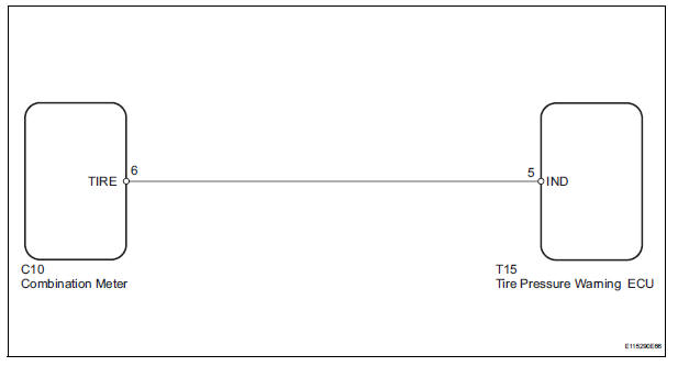
WIRING DIAGRAM
INSPECTION PROCEDURE
NOTICE: When replacing the tire pressure warning ECU, read the transmitter IDs stored in the old ECU using the intelligent tester and write them down before removal.
It is necessary to perform initialization (See page TW-23) after registration (See page TW-20) of the transmitter IDs into the tire pressure warning ECU, after the ECU has been replaced.
HINT: This procedure must be performed according to the PROBLEM SYMPTOMS TABLE.
1 CHECK HARNESS AND CONNECTOR (COMBINATION METER - TIRE PRESSURE WARNING ECU)
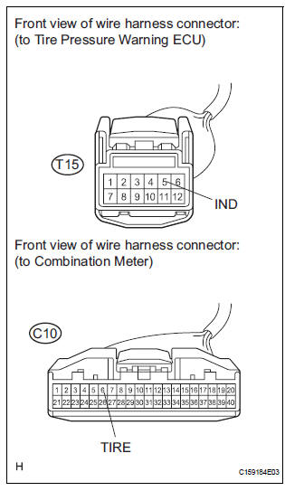
(a) Disconnect the C10 combination meter connector.
(b) Disconnect the T15 tire pressure warning ECU connector.
(c) Measure the resistance according to the value(s) in the table below.
Standard resistance 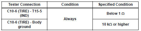

2 INSPECT COMBINATION METER

(a) Disconnect the connector from the tire pressure warning ECU.
(b) Turn the ignition switch to the ON position, and check if the tire pressure warning light illuminates.
Result 

REPLACE TIRE PRESSURE WARNING ECU (See page TW-87)
 Tire Pressure Warning Reset Switch Circuit
DESCRIPTION
The ECU enters the initialization mode and performs initialization
automatically, when the tire pressure
warning ECU receives the signal from the tire pressure warning reset switch. If ...
 ECU Power Source Circuit
DESCRIPTION
This is the power source for the tire pressure warning ECU.
WIRING DIAGRAM
INSPECTION PROCEDURE
NOTICE:
When replacing the tire pressure warning ECU, read the transmitter IDs
st ...
Other materials:
Removing the second seats
Removing the second outside seats (Tip-up seats)
Pull the armrests up.
Pull the seatback adjustment
lever and fold down the seatback.
The cushion will tip up.
Slide the seat forward to a lock position.
Pull the release lever under
the cushion and simultaneously
lift the ...
Transfer oil
ON-VEHICLE INSPECTION
1. INSPECT TRANSFER OIL
(a) Remove the No. 1 plug and gasket.
(b) Check the oil level is within 0 - 5 mm (0 - 0.20 in.)
below the lowest end of the hole for No. 1 plug.
NOTICE:
When changing oil, recheck the oil level after
driving.
Excessively large or small ...
Cooling fan motor
On-vehicle inspection
1. No. 1 Cooling fan motor
(A) check that the motor turns smoothly when the
battery is connected to the fan motor connector.
(B) measure the current while the motor is turning.
Standard current:
11.8 To 14.8 A at 20°c (68°f)
if the result is not as specified, r ...
