Toyota Sienna Service Manual: ECU Power Source Circuit
DESCRIPTION
This circuit provides power to operate the theft deterrent (warning) ECU.
WIRING DIAGRAM
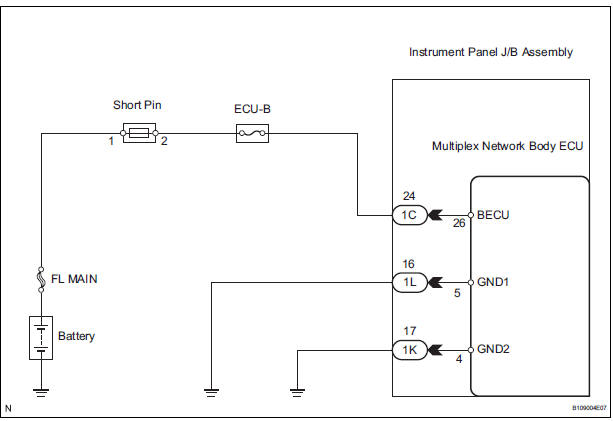
INSPECTION PROCEDURE
1 INSPECT FUSE (ECU-B)
- Remove the ECU-B fuse from the engine room J/B.
- Measure the resistance.
Standard resistance: Below 1 Ω
2 CHECK INSTRUMENT PANEL J/B ASSEMBLY (POWER SOURCE)
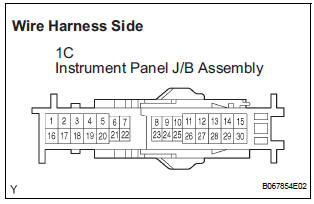
- Disconnect the 1C J/B connector.
- Measure the voltage according to the value(s) in the table below.
Standard voltage
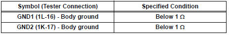
3 CHECK HARNESS AND CONNECTOR (INSTRUMENT PANEL J/B ASSEMBLY - BODY GROUND)
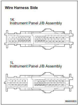
- Disconnect the 1K and 1L J/B connector.
- Measure the resistance according to the value(s) in the table below.
Standard resistance
REPLACE INSTRUMENT PANEL J/B ASSEMBLY
 Security Indicator Light Circuit
DESCRIPTION
Even when the theft deterrent system is in the disarmed state, the security
indicator blinks due to a signal
output from the immobiliser system. The security indicator blinks continuou ...
 Engine hood courtesy
switch
Engine hood courtesy
switch
Inspection
1. INSPECT ENGINE HOOD COURTESY SWITCH
Measure the resistance according to the value(s) in
the table below.
Standard resistance
If the result is not as specified, r ...
Other materials:
Initialization
1. RESET
When the back door lock is replaced:
The power back door ECU cannot receive a switch
signal from the lock. This may cause the power
back door system to enter fail-safe mode and DTC
B2215 to set, and also make the system disabled.
When the lock is replaced, be sure to perform t ...
Open in Rear Curtain Shield Squib RH Circuit
DTC B1631/84 Open in Rear Curtain Shield Squib RH Circuit
DESCRIPTION
The rear curtain shield squib RH circuit consists of the center airbag sensor
assembly and the curtain
shield airbag assembly RH.
The circuit instructs the SRS to deploy when deployment conditions are met.
DTC B1631/84 ...
SFR Solenoid Circuit
DESCRIPTION
The solenoid comes on when signals are received from the ECU and controls the
pressure acting on the
wheel cylinders, thus controlling brake force.
WIRING DIAGRAM
INSPECTION PROCEDURE
1 RECONFIRM DTC
HINT:
These codes are detected when a problem is identified in the
...
