Toyota Sienna Service Manual: ECU Power Source Circuit
DESCRIPTION
The position control ECU and switch assembly (power seat control switch and ECU) is contained in the switch assembly.
During manual operation, only one switch signal is accepted. If signals are input from 2 or more switches simultaneously, all of them are ignored, except when signals are input from the front vertical switch and lifter switch simultaneously. In this case, the signal from the lifter will operate.
During automatic operation, a manual switch input will override any other operations, i.e. automatic operations will stop and the manual input operation only will be accepted. For example, if a manual switch input is activated during a seat store/restore operation, the previous operation will cease and manual operation will be performed. After the manual operation is performed, the previous automatic operation will not resume.
The power mirror store/restore operation is unaffected by manual switch inputs.
The front power seat switch does not allow the restore operation of the power seat when the system detects that the voltage of terminal SYSB is less than 8.0 +- 0.5 V for 30 msec. or is more than 10 +- 0.5 V for 30 msec.
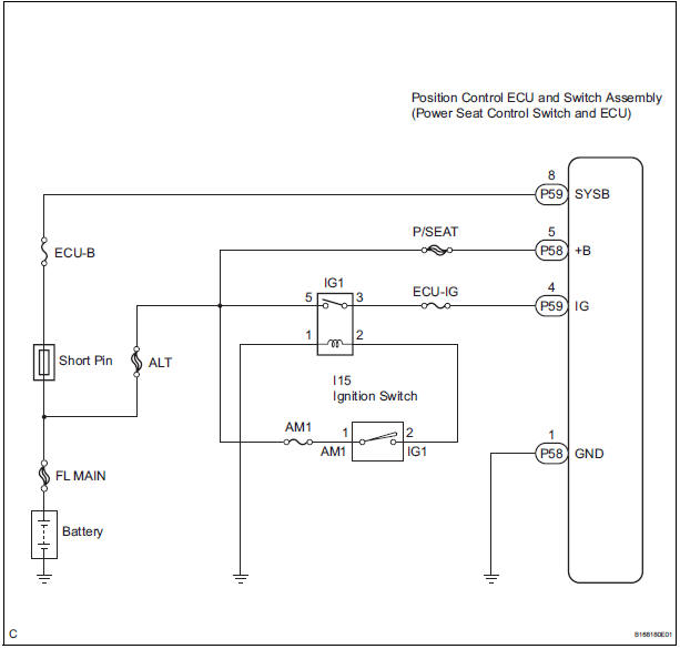
This circuit is the power source circuit for the position control ECU and switch assembly (power seat control switch and ECU).
HINT:
- Manual adjustment of the slide and reclining can be performed even when the front power seat switch is not functional if current is allowed to flow into terminals +B and SYSB.
- The lumber support function can always be used because its circuit does not include the ECU and differs from other functions (reclining, slide, lifter, and front vertical functions.)
WIRING DIAGRAM
INSPECTION PROCEDURE
1 INSPECT POSITION CONTROL ECU AND SWITCH ASSEMBLY (POWER SEAT CONTROL SWITCH AND ECU POWER SOURCE CIRCUIT)
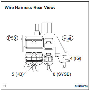
- Disconnect the position control ECU and switch assembly connectors.
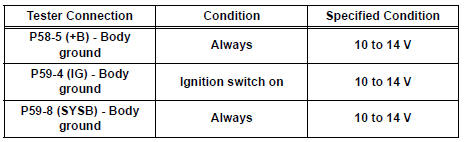
- Measure the voltage according to the value(s) in the table below.
Standard voltage
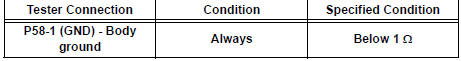
2 INSPECT POSITION CONTROL ECU AND SWITCH ASSEMBLY (POWER SEAT CONTROL SWITCH AND ECU GROUND CIRCUIT)
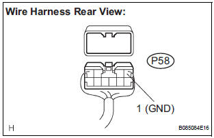
- Measure the resistance according to the value(s) in the table below.
Standard resistance
PROCEED TO NEXT CIRCUIT INSPECTION SHOWN IN PROBLEM SYMPTOMS TABLE
 Driving Position Memory Switch Circuit (w/ Memory)
DESCRIPTION
The seat memory switch sends signals to the outer mirror control ECU LH via
the multiplex
communication system to memorize a given seat position. This memory system does
not use a po ...
 Seat heater system
PARTS LOCATION
...
Other materials:
Installation
1. INSTALL STARTER ASSEMBLY
(a) Install the starter with the 2 bolts.
Torque: 37 N*m (380 kgf*cm, 26 ft.*lbf) for bolt
(b) Connect the starter connector.
(c) Install the terminal nut and cover the nut with the
cap.
Torque: 9.8 N*m (100 kgf*cm, 7 ft.*lbf) for nut
2. INSTALL NO. 1 ...
Release Actuator Circuit
DESCRIPTION
The fold seat control ECU receives a switch operation signal from the fold
seat switch and activates the
release actuator. The release actuator releases the lock of the stowed seat
based on a drive voltage
received from the ECU.
WIRING DIAGRAM
INSPECTION PROCEDURE
1 INSPECT ...
Disassembly
1. REMOVE AIR REFINER ELEMENT
(a) Release the 2 claw fittings and remove the air filter
sub-assembly.
(b) Remove the air refiner element from the air filter
cover plate.
2. REMOVE COOLING UNIT DAMPER SERVO SUBASSEMBLY
(a) Remove the 3 screws and the cooling unit damper
servo sub-a ...
