Toyota Sienna Service Manual: Driving Position Memory Switch Circuit (w/ Memory)
DESCRIPTION
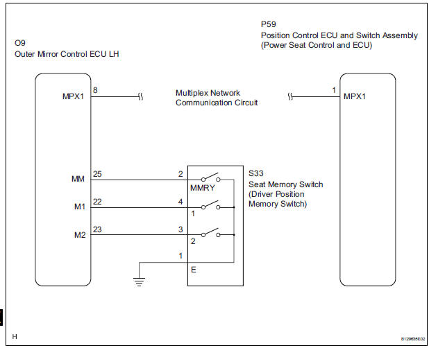
The seat memory switch sends signals to the outer mirror control ECU LH via the multiplex communication system to memorize a given seat position. This memory system does not use a position sensor. The seat position is detected by counting pulses that are output when the motor turns. If there is no pulse output from the motor, the motor will stop operating. The seat memory switch is later used to send signals to the front power seat switch to return the seat to one of the memorized positions.
The power seat memory operation can be performed only when the ignition switch is on and the shift lever is in the P position.
WIRING DIAGRAM
INSPECTION PROCEDURE
1 READ VALUE OF INTELLIGENT TESTER
- Connect the intelligent tester (with CAN VIM) to the DLC3.
- Turn the ignition switch on.
- Read the DATA LIST.
D_SEAT (Position control ECU and switch assembly)
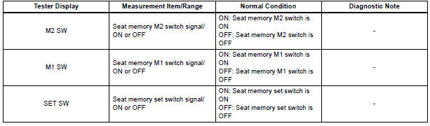
OK: Condition status can be displayed.
PROCEED TO NEXT CIRCUIT INSPECTION SHOWN IN PROBLEM SYMPTOMS TABLE
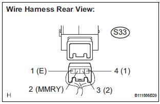
2 INSPECT SEAT MEMORY SWITCH (DRIVING POSITION MEMORY SWITCH)
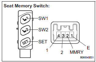
- Remove the seat memory switch.
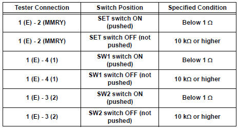
- Measure the resistance according to the value(s) in the table below.
Standard resistance
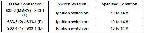
3 CHECK HARNESS AND CONNECTOR (SEAT MEMORY SWITCH CIRCUIT)
- Measure the voltage according to the value(s) in the table below.
Standard voltage
PROCEED TO NEXT CIRCUIT INSPECTION SHOWN IN PROBLEM SYMPTOMS TABLE
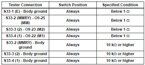
4 CHECK HARNESS AND CONNECTOR (OUTER MIRROR CONTROL ECU LH - SEAT MEMORY SWITCH)
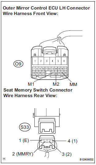
- Disconnect outer mirror control ECU LH connector.
- Measure the resistance according to the value(s) in the table below.
Standard resistance
REPLACE OUTER MIRROR CONTROL ECU LH
 Power Seat Motor Circuit
DESCRIPTION
When the power seat control switch is operated, a command signal is sent to
the position control ECU
and switch assembly (power seat control switch and ECU). The front power seat
swi ...
 ECU Power Source Circuit
DESCRIPTION
The position control ECU and switch assembly (power seat control switch and
ECU) is contained in the
switch assembly.
During manual operation, only one switch signal is accepted. If ...
Other materials:
Approach warning
When your vehicle is too close to a vehicle ahead, and sufficient automatic
deceleration via the cruise control is not possible, the display
will flash and the buzzer will sound to alert the driver. An example of
this would be if another driver cuts in front of you while you are following
a vehi ...
Rear side sunshades
Rear door window
Rear quarter window
Pull the tab up.
Secure the sunshade using the hooks.
To retract the sunshade, pull the tab up slightly to unhook the sunshade,
and lower the sunshade slowly.
NOTICE
To ensure normal operation of the rear sunshades, observe ...
Warning lights and
indicators
The warning lights and indicators on the instrument cluster and
center panel inform the driver of the status of the vehicle’s various
systems.
For the purpose of explanation, the following illustration displays
all warning lights and indicators illuminated.
Vehicles with monochrome displ ...
