Toyota Sienna Service Manual: On-vehicle inspection
1. CHECK POWER SEAT FUNCTION
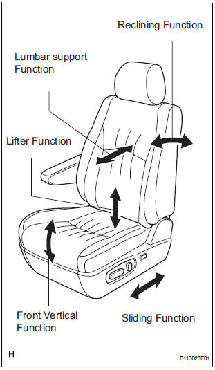
- Check the basic functions.
- Operate the power seat switches and check the following seat functions:
- Sliding
- Reclining
- Front vertical (Driver side seat only)
- Lifter (Driver side seat only)
- Lumbar support (Driver side seat only)
2. CHECK POWER SEAT MOTOR ASSEMBLY (SLIDING, FRONT VERTICAL, LIFTER AND RECLINING FUNCTIONS)
- Inspect the PTC operation inside the power seat motor.
NOTICE: The inspection should be performed with the seat installed in the vehicle.
- Move the seat to any of the maximum position by operating the power seat switch, and keep the seat there for approximately 60 seconds.
- Try to move the power seat beyond the
maximum position using the power seat switch.
Measure the time needed for shutting off the electrical current after the lumbar support stops moving. (motor operation sound will stop, inspection of current shut-off).
Standard: 4 to 90 seconds
- Release the power seat switch, and wait for approximately 60 seconds.
- Operate the power seat switch to move the seat to the opposite position and check that the motor operates.
3. CHECK LUMBAR SUPPORT ADJUSTER ASSEMBLY
- Inspect the PTC operation inside the power seat motor.
NOTICE: The inspection should be performed with the seat installed in the vehicle.
- Move the lumbar support to either the foremost or rearmost position by operating the lumbar support switch, and keep it there for approximately 60 seconds.
- Try to move the lumbar support beyond the
maximum position using the switch. Measure
the time needed for shutting off the electrical
current after the lumbar support stops moving.
(motor operation sound will stop, inspection of current shut-off).
Standard: 4 to 90 seconds
- Release the lumbar support switch, and wait for approximately 60 seconds.
- Operate the lumbar support switch to move the lumbar support to the opposite position and check that the motor operates.
4. CHECK MEMORY AND REACTIVATION FUNCTION (w/ MEMORY)
- Turn the ignition switch on and move the shift lever into the P position.
- Move the seat into the foremost position and uppermost position using each seat switch.
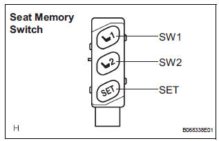
- Check that the buzzer sounds for 0.5 seconds. The seat position is recorded when the SW1 switch is pressed while also pressing the SET switch.
- Move the seat out of the foremost position and uppermost position using each seat switch.
- Check that the buzzer sounds for 0.5 seconds. The seat position is recorded when the SW2 switch is pressed while also pressing the SET switch.
- Check that the buzzer sounds for 0.1 seconds and the seat automatically moves into the foremost position and uppermost position (SET positions) when the SW1 switch is pressed.
- Check that the buzzer sounds for 0.1 seconds and the seat automatically moves out of the foremost position and uppermost position (SET positions) when the SW2 switch is pressed.
- Check that the seat automatically moves into the SET position when the SW1 or SW2 switch is pressed within 30 seconds after the ignition switch is turned off, the key is pulled out from the key cylinder and the driver side door is opened.
- Move the seat either forward or back as far as the
seat will move, and disconnect the negative terminal
of the battery while the memory switch is pressed.
Then leave the seat at the position for 3 minutes to erase the seat position memory.
- Move the seat into all the maximum positions (front/ rear and up/down) using each seat switch.
- Check that the seat does not move (the seat position is not recorded) by performing the following steps while pressing the SET switch. Press either the SW1 switch or the SW2 switch after pressing SW1 and SW2 at the same time.
 Data list / active test
1. DATA LIST
HINT:
Using the intelligent tester's DATA LIST allows the status
of a switch, sensor, actuator and other items to be read
without removing any parts. Reading the DATA LIST
early in t ...
 Power Seat Motor Circuit
DESCRIPTION
When the power seat control switch is operated, a command signal is sent to
the position control ECU
and switch assembly (power seat control switch and ECU). The front power seat
swi ...
Other materials:
Removal
HINT:
Use the same procedures for the RH side and LH side.
The procedures listed below are for the LH side.
1. PRECAUTION
CAUTION: Be sure to read "PRECAUTION" thoroughly before
servicing.
2. DISCONNECT CABLE FROM NEGATIVE BATTERY
TERMINAL
CAUTION:
Wait for 90 s ...
Power Window cannot be Operated by Wireless Operation
DESCRIPTION
When the switch on the transmitter is operated during normal operating
conditions, the
multiplex network body ECU sends a request signal to the master switch and the
regulator switches which
then drive the applicable power window motors.
INSPECTION PROCEDURE
1 CHECK WIRELESS DOO ...
Inspection
1. INSPECT HEATED OXYGEN SENSOR (for Bank 1
Sensor 2)
(a) Measure the resistance of the sensor.
Standard resistance
If the resistance is not as specified, replace the
sensor.
2. INSPECT HEATED OXYGEN SENSOR (for Bank 2
Sensor 2)
(a) Measure the resistance of the sensor.
Standard r ...
