Toyota Sienna Service Manual: Engine Coolant Temperature Circuit Range / Performance Problem
DTC P0116 Engine Coolant Temperature Circuit Range / Performance Problem
DESCRIPTION
Refer to DTC P0115
|
DTC No. |
DTC Detection Condition |
Trouble Area |
|
P0116 |
ECTs as listed below are nearly same (2 trip detection
logic):
|
|
ECTs as listed below are nearly same when engine is
started at higher than 60C (140F) of ECT (2 trip
detection logic)
|
||
When either of following conditions is met (2 trip
detection logic):
|
MONITOR DESCRIPTION
The ECT sensor is used to monitor the ECT. The ECT sensor has a built-in thermistor with a resistance that varies according to the temperature of the engine coolant. When the ECT becomes low, the resistance of the thermistor increases. When the temperature becomes high, the resistance drops. These variations in the resistance are reflected in the voltage output from the ECT sensor.
The ECM monitors the sensor voltage and uses this value to calculate the ECT. If the sensor voltage output deviates from the normal operating range, the ECM interprets this deviation as a malfunction in the ECT sensor and sets the DTC.
Examples:
- Upon starting the engine, the ECT is between 35C and 60C (95F and 140F). If the ECT remains within 3C (5.4F) of the stating temperature after driving for 250 seconds, the DTC is set (2 trip detection logic).
- Upon starting the engine, the ECT is over 60C (140F). If the ECT remains within 1C (1.8F) of the starting temperature after driving for 250 seconds, the DTC is set (6 trip detection logic).
MONITOR STRATEGY
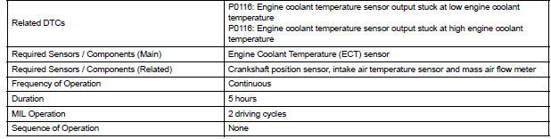
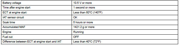
TYPICAL ENABLING CONDITIONS
All:

ECT sensor cold start monitor:
ECT sensor soak monitor:
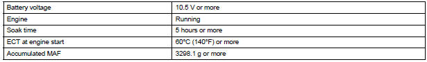
TYPICAL MALFUNCTION THRESHOLDS
ECT sensor cold start monitor:

ECT sensor soak monitor:

COMPONENT OPERATING RANGE

INSPECTION PROCEDURE
HINT:
- If any of DTC P0115, P0117, P0118 or P0125 are set simultaneously with DTC P0116, the ECT sensor may have an open or a short circuit. Troubleshoot those DTCs first.
- Read freeze frame data using the intelligent tester. The ECM records vehicle and driving condition information as freeze frame data the moment a DTC is stored. When troubleshooting, freeze frame data can be helpful in determining whether the vehicle was running or stopped, whether the engine was warmed up or not, whether the air-fuel ratio was lean or rich, as well as other data recorded at the time of a malfunction.
1 CHECK ANY OTHER DTCS OUTPUT (IN ADDITION TO DTC P0166)
- Connect the intelligent tester to the DLC3.
- Turn the ignition switch to the ON position.
- Turn the tester on.
- Enter the following menus: DIAGNOSIS / ENHANCED II / DTC INFO / CURRENT CODES.
- Read the DTC.
Result

2 INSPECT THERMOSTAT
- Remove the thermostat.
- Check the valve opening temperature of the thermostat.
Standard: 80 to 84C (176 to 183F)
HINT: In addition to the above check, confirm that the valve is completely closed when the temperature is below the standard.
- Reinstall the thermostat
REPLACE ENGINE COOLANT TEMPERATURE SENSOR
 Engine Coolant Temperature Circuit
DTC P0115 Engine Coolant Temperature Circuit
DTC P0117 Engine Coolant Temperature Circuit Low Input
DTC P0118 Engine Coolant Temperature Circuit High Input
DESCRIPTION
A thermistor is built into t ...
 Engine Coolant Temperature / Intake Air Temperature
Correlation
Engine Coolant Temperature / Intake Air Temperature
Correlation
DTC P011B Engine Coolant Temperature / Intake Air Temperature
Correlation
DESCRIPTION
The ECM calculates the difference between the readings of the coolant
temperature sensor and intake air
temp ...
Other materials:
ABS Warning Light Remains ON
DESCRIPTION
If any of the following is detected, the ABS warning light remains on.
The skid control ECU connectors are disconnected from the skid control
ECU.
There is a malfunction in the skid control ECU internal circuit.
There is an open in the harness between the combination meter an ...
Reassembly
1. INSTALL FUEL PRESSURE REGULATOR ASSEMBLY
(a) Apply a light coat of gasoline or spindle oil to the 2
new O-rings, and install it to the fuel pressure
regulator.
(b) Apply a light coat of gasoline or spindle oil to the 2
O-rings again, and install the fuel pressure regulator
to the No. ...
Rear Occupant Classification Sensor RH Collision
Detection
DTC B1788 Rear Occupant Classification Sensor RH Collision
Detection
DESCRIPTION
DTC B1788 is output when the occupant classification ECU receives a collision
detection signal sent by
the rear occupant classification sensor RH if an accident occurs.
DTC B1788 is also output when the front s ...
