Toyota Sienna Service Manual: On-vehicle inspection
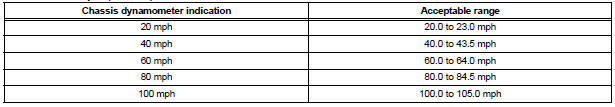
1. INSPECT SPEEDOMETER
- Check the operation.
- Using a speedometer tester, check the speedometer indication according to the table below.
Reference: mph (U.S.A.)
Reference: km/h (Canada)
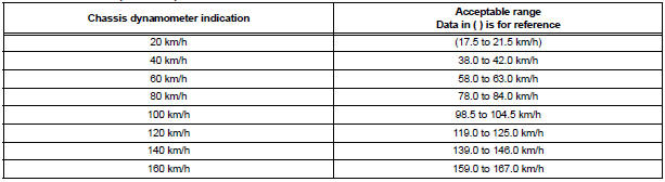
NOTICE: Tire wear as well as over or under inflation will cause errors.
- Check the deviation from the acceptable value
of the speedometer indication.
Reference: Less than 0.5 km/h (0.3 mph)
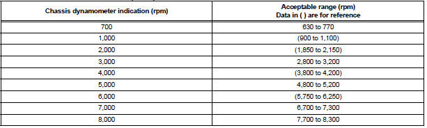
2. INSPECT TACHOMETER
- Check the operation.
- Connect the tune-up test tachometer, and start the engine.
- Compare the the test results with the tachometer indications.
Reference: DC 13.5 V, at 25C (77F)
3. INSPECT FUEL RECEIVER GAUGE
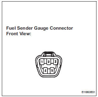
- Disconnect the connector from the sender gauge.
- Turn the ignition switch to the ON position, then check the position of the receiver gauge needle.
OK: Needle position is on (EMPTY).
- Connect the terminals 2 and 3 on the wire harness side connector of the fuel sender gauge.
- Turn the ignition switch to the ON position, then check the position of the receiver gauge needle.
OK: Needle position is on (FULL).
4. INSPECT FUEL LEVEL WARNING LIGHT
- Disconnect the connector from the sender gauge.
- Turn the ignition switch to the ON position, then check the fuel level needle indicates EMPTY and the fuel level warning light comes on.
OK: Fuel level warning light comes on.
5. INSPECT OIL PRESSURE WARNING LIGHT
- Disconnect the connector from the low oil pressure switch.
- Turn the ignition switch to the ON position.
- Ground the terminal of the wire harness side connector, then check the low oil pressure warning light.
OK: OIL PRESSURE warning light comes on.
6. INSPECT OIL CHANGE REMINDER LIGHT RESETTING PROCEDURE
CONDITION:
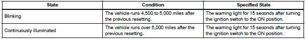
- Set the window to the odometer.
- Turn the ignition switch off.
- While pressing the reset switch, turn the ignition switch to the ON position. Keep pressing the reset switch for at least 5 seconds to complete the reset procedure. Check that the "000000" is displayed on the odometer.
HINT: If the ignition switch is turned off during the reset procedure; LCD: off If the reset switch is not pressed for at least 5 seconds during the reset procedure; LCD: Return to odometer
TYPICAL ENABLING CONDITIONS
| The monitor will run whenever these DTCs are not present | P0011, P0012 (VVT System 1-Advance, Retard), P0021, P0022 (VVT System 2- Adavance, Retard), P0031, P0032, P0051, P0052 (A/F Sensor Heater Sensor 1), P0037, P0038, P0057, P0058 (O2 Sensor heater Sensor 2), P0100, P0101, P0102, P0103 (MAF Sensor), P0115, P0116, P0117, P0118 (ECT Sensor), P0120, P0121, P0122, P0123, P0220, P0222, P0223 , P2135 (TP Sensor), P0125 (Insufficient ECT for Closed Loop), P0136, P0156 (O2 Sensor 2), P0171,P0172 (Fuel System), P0300, P0301, P0302, P0303, P0304, P0305, P0306 (Misfire), P0335 (CKP Sensor), P0340 (CMP Sensor), P0351, P0352, P0353, P0354, P0355, P0356 (Ignitor), P0500 (VSS), P2196, P2198 (A/F Sensor (Rationality)), P2A00, P2A03 (A/ F Sensor (Slow Response)) |
| Battery voltage | 11 V or more |
| IAT | -10C (14F) or more |
| ECT | 75C (167F) or more |
| Atmospheric pressure | 0.75 or more |
| Idle | OFF |
| Engine RPM | Less than 3200 rpm |
| A/F sensor | Activated |
| Fuel system status | Closed loop |
| Engine load | 10 to 70% |
| All of the following conditions are met | Conditions 1, 2 and 3 |
| 1. Mass air flow rate | 5 to 60 g/sec |
| 2. Front catalyst temperature (estimated) | 600 to 750C (1112 to 1382F) |
| 3. Rear catalyst temperature (estimated) | 100 to 900C (212 to 1652F) |
| Rear HO2S monitor | Completed |
| Shift position | 4th or more |
TYPICAL MALFUNCTION THRESHOLDS
| Oxygen Storage Capacity (OSC) of catalyst | Less than 0.046 g (0.000101 lb) |
MONITOR RESULT
Refer to CHECKING MONITOR STATUS.
CONDITIONING FOR SENSOR TESTING
HINT: Perform the operation with the engine speeds and durations described below prior to checking the waveforms of the A/F and HO2 sensors. This is in order to activate the sensors sufficiently to obtain the appropriate inspection results.
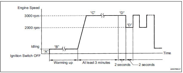
- Connect the intelligent tester to the DLC3 (Procedure "A").
- Start the engine and warm it up with all the accessories switched off, until the engine coolant temperature stabilizes (Procedure "B").
- Run the engine at an engine speed of between 2500 rpm and 3000 rpm for at least 3 minutes (Procedure "C").
- While running the engine at 3000 rpm for 2 seconds and at 2000 rpm for 2 seconds, check the waveforms of the A/F and HO2 sensors using the tester (Procedure "D").
HINT:
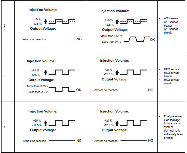
- If either of the voltage outputs of the Air-Fuel Ratio (A/F) or Heated Oxygen (HO2) sensor does not fluctuate, or either of the sensors makes a noise, the sensor may be malfunctioning.
- If the voltage outputs of both the sensors remain lean or rich, the air-fuel ratio may be extremely lean or rich. In such cases, perform the following A/F CONTROL using the intelligent tester.
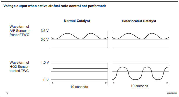
- If the Three-Way Catalytic Converter (TWC) has deteriorated, the HO2 sensor (located behind the TWC) voltage output fluctuates up and down frequently, even under normal driving conditions (active air-fuel ratio control is not performed).
1. A/F CONTROL
HINT: Intelligent tester only: Malfunctioning areas can be identified by performing the A/F CONTROL function provided in the ACTIVE TEST. The A/F CONTROL function can help to determine whether the Air-Fuel Ratio (A/F) sensor, Heated Oxygen (HO2) sensor and other potential trouble areas are malfunctioning.
The following instructions describe how to conduct the A/F CONTROL operation using an intelligent tester.
- Connect the intelligent tester to the DLC3.
- Start the engine and turn the tester on.
- Warm up the engine at an engine speed of 2500 rpm for approximately 90 seconds.
- On the tester, select the following menu items: DIAGNOSIS / ENHANCED OBD II / ACTIVE TEST / A/F CONTROL.
- Perform the A/F CONTROL operation with the engine in an idling condition (press the RIGHT or LEFT button to change the fuel injection volume).
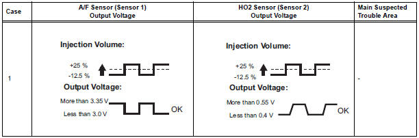
- Monitor the voltage outputs of the A/F and HO2 sensors (AFS B1S1 and O2S B1S2 or AFS B2S1 and O2S B2S2) displayed on the tester.
HINT:
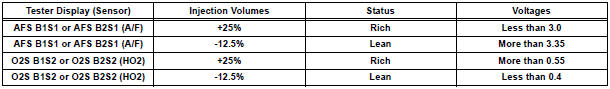
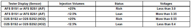
- The A/F CONTROL operation lowers the fuel injection volume by 12.5% or increases the injection volume by 25%.
- Each sensor reacts in accordance with increases and decreases in
the fuel injection volume.
Standard voltage
CAUTION: The Air-Fuel Ratio (A/F) sensor has an output delay of a few seconds and the Heated Oxygen (HO2) sensor has a maximum output delay of approximately 20 seconds.
- Following the A/F CONTROL procedure enables technicians to check and graph the voltage outputs of both the A/F and HO2 sensors.
- To display the graph, select the following menu items on the tester: DIAGNOSIS / ENHANCED OBD II / ACTIVE TEST / A/F CONTROL / USER DATA / AFS B1S1 and O2S B1S2 or AFS B2S1 and O2S B2S2. Press the YES button and then the ENTER button. Then press the F4 button.
INSPECTION PROCEDURE
HINT: Read freeze frame data using the intelligent tester. The ECM records vehicle and driving condition information as freeze frame data the moment a DTC is stored. When troubleshooting, freeze frame data can be helpful in determining whether the vehicle was running or stopped, whether the engine was warmed up or not, whether the air-fuel ratio was lean or rich, as well as other data recorded at the time of a malfunction.
1 CHECK ANY OTHER DTCS OUTPUT (IN ADDITION TO DTC P0420 AND/OR P0430)
- Connect the intelligent tester to the DLC3.
- Turn the ignition switch to the ON position and turn the tester on.
- Select the following menu items: DIAGNOSIS / ENHANCED OBD II / DTC INFO / CURRENT CODES.
- Read the DTCs.
Result

HINT: If any DTCs other than P0420 or P0430 are output, troubleshoot those DTCs first.
2 PERFORM ACTIVE TEST BY INTELLIGENT TESTER (A/F CONTROL)
- Connect the intelligent tester to the DLC3.
- Start the engine and turn the tester on.
- Warm up the engine at an engine speed of 2500 rpm for approximately 90 seconds.
- Select the following menu items on the tester: DIAGNOSIS / ENHANCED OBD II / ACTIVE TEST / A/F CONTROL.
- Perform the A/F CONTROL operation with the engine in an idling condition (press the RIGHT or LEFT button to change the fuel injection volume).
- Monitor the voltage outputs of the A/F and HO2 sensors (AFS B1S1 and O2S B1S2 or AFS B2S1 and O2S B2S2) displayed on the tester.
HINT:
- The A/F CONTROL operation lowers the fuel injection volume by 12.5% or increases the injection volume by 25%.
- Each sensor reacts in accordance with increases and decreases in the fuel injection volume.
Standard voltage
Result
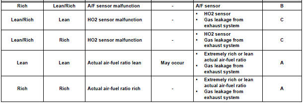
Lean: During A/F CONTROL, the A/F sensor output voltage (AFS) is consistently more than 3.35 V, and the HO2 sensor output voltage (O2S) is consistently less than 0.4 V.
Rich: During A/F CONTROL, the AFS is consistently less than 3.0 V, and the O2S is consistently more than 0.55 V.
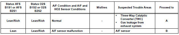
Lean/Rich: During A/F CONTROL of the ACTIVE TEST, the output voltage of the HO2 sensor alternates correctly.
3 INSPECT FOR EXHAUST GAS LEAK
OK: No gas leakage
REPLACE THREE-WAY CATALYTIC CONVERTER (EXHAUST MANIFOLD LH OR RH)
- Entire Combination Meter does not Operate
- Speedometer Malfunction
- Tachometer Malfunction
- Fuel Receiver Gauge Malfunction
- Engine Coolant Temperature Receiver Gauge Malfunction
- Driver Side Seat Belt Warning Light does not Operate
- Operating Light Control Rheostat does not Change Light Brightness
- Meter Illumination is Always Dark
- Meter Illumination does not Dim at Night
 Data list / active test
1. DATA LIST
Using the intelligent tester to read the Data List allows
the values or states of switches, sensors, actuators and
other items to be read without removing any parts. This
non-intrusiv ...
 Entire Combination Meter does not Operate
DESCRIPTION
This is the power source circuit to operate the combination meter assembly.
WIRING DIAGRAM
INSPECTION PROCEDURE
1 INSPECT COMBINATION METER ASSEMBLY
Disconnect the C10 conn ...
Other materials:
Slide door lock
INSPECTION
1. INSPECT SLIDE DOOR LOCK REMOTE CONTROL SUB-ASSEMBLY LH
Inspect the resistance of the switch.
Resistance
If the result is not as specified, replace the control
assembly.
2. INSPECT SLIDE DOOR LOCK REMOTE CONTROL SUB-ASSEMBLY RH
Inspect the resistance of the swit ...
VIN not Programmed or Mismatch - ECM / PCM
DESCRIPTION
DTC P0630 is set when the Vehicle Identification Number (VIN) is not stored
in the Engine Control Module
(ECM) or the input VIN is not accurate. Input the VIN with the intelligent
tester.
MONITOR STRATEGY
TYPICAL ENABLING CONDITIONS
TYPICAL MALFUNCTION THRESHOLDS ...
Catalyst System Efficiency Below Threshold
MONITOR DESCRIPTION
The ECM uses the sensors mounted in front of and behind the three-way
catalyst (TWC) to monitor its
efficiency. The first sensor, an Air Fuel ratio (A/F) sensor, sends pre-catalyst
A/F ratio information to the
ECM. The second sensor, a heated oxygen sensor (O2S), sends ...
