Toyota Sienna Service Manual: Speedometer Malfunction
DESCRIPTION
Factors that affect the indicated vehicle speed include tire size, tire inflation, and tire wear. The speed indicated on the speedometer has an allowable margin of error. This can be tested using a speedometer tester (calibrated chassis dynamometer). For details about testing and the margin of error, see the reference chart.
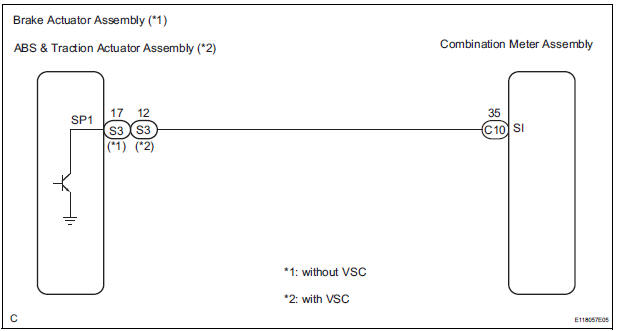
WIRING DIAGRAM
INSPECTION PROCEDURE
NOTICE: If the vehicle speed is outside the allowable range when tested, perform the following procedure.
1 PERFORM ACTIVE TEST BY INTELLIGENT TESTER
- Connect the tester to the DLC3.
- Turn the ignition switch to the ON position.
- Turn the tester ON.
- Enter the following menus: DIAGNOSIS / OBD/MOBD / METER / ACTIVE TEST
- Check the operation by referring to the values in the table below.
METER:

*1: for U.S.A.
*2: Except for U.S.A.
OK: Needle indication is within the allowable range.
2 READ VALUE OF INTELLIGENT TESTER
- Connect the intelligent tester to the DLC3.
- Turn the ignition switch to the ON position.
- Turn the tester ON.
- Enter the following menus: DIAGNOSIS / OBD/MOBD / METER / DATA LIST.
- Check the values by referring to the values in the table below.
METER:

OK: Vehicle speed displayed on the tester is almost the same as the actual vehicle speed measured using a speedometer tester (calibrated chassis dynamometer).
REPLACE COMBINATION METER ASSEMBLY
3 READ VALUE OF INTELLIGENT TESTER
- Connect the intelligent tester to the DLC3.
- Turn the ignition switch to the ON position.
- Turn the tester ON.
- Enter the following menus: DIAGNOSIS / ABS/TRAC/ VSC / DATA LIST.
- Check the values by referring to the values in the table below.
ABS/TRAC/VSC:

OK: Vehicle speed displayed on the tester is almost the same as the actual vehicle speed measured using a speedometer tester (calibrated chassis dynamometer).
4 INSPECT COMBINATION METER ASSEMBLY
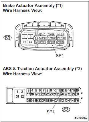
- Disconnect the S3 connector.
- Measure the voltage according to the value(s) in the table below.
Standard voltage
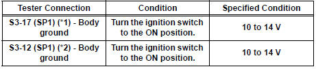
*1: without VSC
*2: with VSC
Result
5 INSPECT COMBINATION METER ASSEMBLY
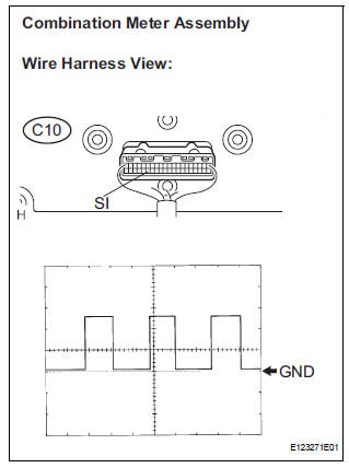
- Check the input signal waveform.
- Remove the combination meter assembly with connector(s) still connected.
- Connect the oscilloscope to terminal C10-35 (SI) and body ground.
- Turn the wheel slowly.
- Check the signal waveform according to the condition(s) in the table below.
OK: The waveform is displayed as shown in the illustration.
HINT: As the vehicle speed increases, the cycle of the signal waveform narrows.
Result
REPLACE COMBINATION METER ASSEMBLY
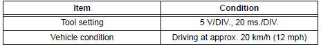
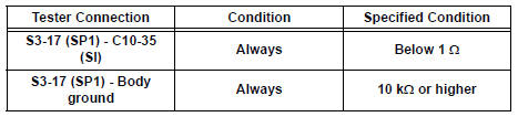
6 CHECK HARNESS AND CONNECTOR (COMBINATION METER - BRAKE ACTUATOR ASSEMBLY)
- Disconnect the S3 and C10 connectors.
- Measure the resistance according to the value(s) in the table below.
Standard resistance
REPLACE COMBINATION METER ASSEMBLY
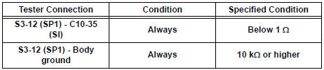
7 CHECK HARNESS AND CONNECTOR (COMBINATION METER - ABS & TRACTION ACTUATOR ASSEMBLY)
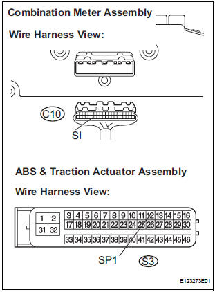
- Disconnect the S3 and C10 connectors.
- Measure the resistance according to the value(s) in the table below.
Standard resistance
REPLACE COMBINATION METER ASSEMBLY
 Entire Combination Meter does not Operate
DESCRIPTION
This is the power source circuit to operate the combination meter assembly.
WIRING DIAGRAM
INSPECTION PROCEDURE
1 INSPECT COMBINATION METER ASSEMBLY
Disconnect the C10 conn ...
 Tachometer Malfunction
DESCRIPTION
The meter CPU receives the engine revolution signal from the ECM via the
direct lines. The meter CPU
displays engine revolution data that is calculated based on the data received
fro ...
Other materials:
ACIS Control Circuit
DESCRIPTION
This circuit opens and closes the Intake Air Control Valve (IACV) in response
to changes in the engine
load in order to increase the intake efficiency (ACIS: Acoustic Control
Induction System).
When the engine speed is between 0 and 4450 rpm and the throttle valve opening
angl ...
Cranking Holding Function Circuit
DESCRIPTION
The system detects the ignition switch's starting signal (STSW) and then
supplies current to the starter
until the ECM judges that the engine has started successfully. The purpose is to
reduce the holding time
of the ignition key.
WIRING DIAGRAM
Refer to DTC P0617.
INSPECTI ...
ECM Communication Circuit Malfunction
DTC C1203/53 ECM Communication Circuit Malfunction
DESCRIPTION
The circuit is used to send TRAC and VSC control information from the skid
control ECU to the ECM, and
engine control information from the ECM to the skid control ECU through the CAN
communication
system.
INSPECTION PROCEDURE
1 ...
