Toyota Sienna Service Manual: Evaporative Emission Control System Leak Detected
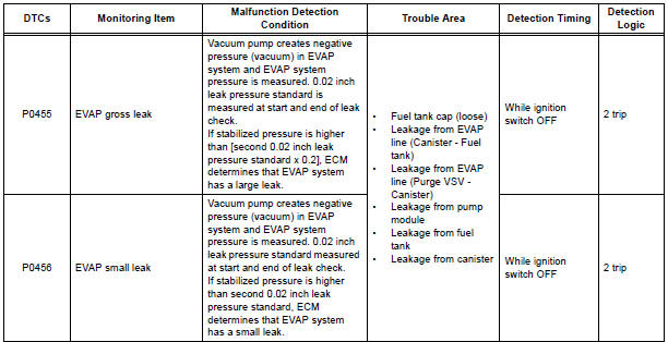
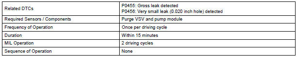
DTC P0455 Evaporative Emission Control System Leak Detected (Gross Leak)
DTC P0456 Evaporative Emission Control System Leak Detected (Very Small Leak)
DTC SUMMARY
DESCRIPTION
The circuit description can be found in the EVAP (Evaporative Emission) System.
INSPECTION PROCEDURE
Refer to the EVAP System.
MONITOR DESCRIPTION
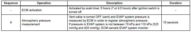
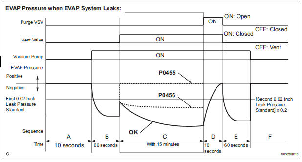
5 hours*1 after the ignition switch is turned off, the electric vacuum pump creates negative pressure (vacuum) in the EVAP (Evaporative Emission) system. The ECM monitors for leaks and actuator malfunctions based on the EVAP pressure.
HINT: *1: If the engine coolant temperature is not below 35C (95F) 5 hours after the ignition switch is turned off, the monitor check starts 2 hours later. If it is still not below 35C (95F) 7 hours after the ignition switch is turned off, the monitor check starts 2.5 hours later.
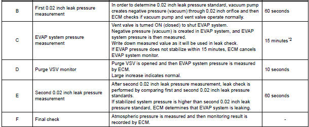
*2: If only a small amount of fuel is in the fuel tank, it takes longer for the EVAP pressure to stabilize.
- P0455: EVAP (Evaporative Emission) gross leak
In operation C, the vacuum pump creates negative pressure (vacuum) in the EVAP system and the EVAP system pressure is measured. If the stabilized system pressure is higher than [second 0.02 inch leak pressure standard x 0.2] (near atmospheric pressure), the ECM determines that the EVAP system has a large leak, illuminates the MIL and sets the DTC (2 trip detection logic). - 2. P0456: EVAP very small leak
In operation C, the vacuum pump creates negative pressure (vacuum) in the EVAP system and the EVAP system pressure is measured. If the stabilized system pressure is higher than second 0.02 inch leak pressure standard, the ECM determines that the EVAP system has a small leak, illuminates the MIL and sets the DTC (2 trip detection logic).
MONITOR STRATEGY
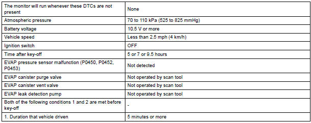
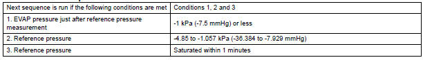
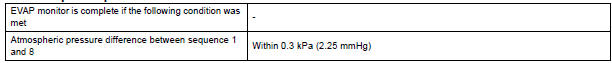
TYPICAL ENABLING CONDITIONS

Key-off monitor sequence 1 to 8
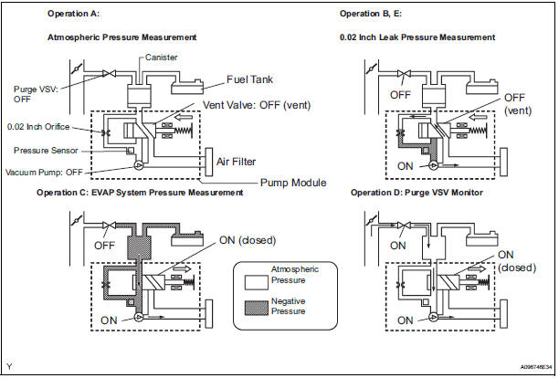
1. Atmospheric pressure measurement

2. First reference pressure measurement
3. EVAP canister vent valve close stuck check

4. Vacuum introduction

5. EVAP canister purge valve close stuck check

6. Second reference pressure measurement

7. Leak check

8. Atmospheric pressure measurement
TYPICAL MALFUNCTION THRESHOLDS
P0455: EVAP gross leak

P0456: EVAP 0.02 inch leak

MONITOR RESULT
Refer to CHECKING MONITOR STATUS
 Evaporative Emission Control System Pressure
DTC P0450 Evaporative Emission Control System Pressure
Sensor / Switch
DTC P0451 Evaporative Emission Control System Pressure
Sensor Range / Performance
DTC P0452 Evaporative Emission Control Syst ...
 Vehicle Speed Sensor "A"
DTC P0500 Vehicle Speed Sensor "A"
DESCRIPTION
The speed sensor detects the wheel speed and sends the appropriate signals to
the skid control ECU.
The skid control ECU converts these ...
Other materials:
System Voltage
DTC P0560 System Voltage
MONITOR DESCRIPTION
The battery supplies electricity to the ECM even when the ignition switch is
off. This power allows the
ECM to store data such as DTC history, freeze frame data and fuel trim values.
If the battery voltage falls
below a minimum level, these memori ...
Diagnostic trouble code chart
HINT:
If a malfunction code is displayed during the DTC check,
check the circuit indicated by the DTC. For details of each
code, turn to the page for the respective "DTC Code" in the
DTC chart.
DTC chart of ABS:
DTC chart of VSC:
...
Tachometer Malfunction
DESCRIPTION
The meter CPU receives the engine revolution signal from the ECM via the
direct lines. The meter CPU
displays engine revolution data that is calculated based on the data received
from the ECM.
WIRING DIAGRAM
INSPECTION PROCEDURE
1 PERFORM ACTIVE TEST BY INTELLIGENT TESTER
...
