Toyota Sienna Service Manual: Evaporator temperature sensor circuit
DESCRIPTION
The evaporator temperature sensor (A/C thermistor) is installed on the evaporator in the air conditioning unit. It detects the temperature of the cooled air that has passed through the evaporator and its signal is used to control the air conditioning. It sends a signal to the A/C amplifier. The resistance of the evaporator temperature sensor (A/C thermistor) changes in accordance with the temperature of the cooled air that has passed through the evaporator. As the temperature decreases, the resistance increases. As the temperature increases, the resistance decreases.
The A/C amplifier applies voltage (5 V) to the evaporator temperature sensor
(A/C thermistor) and reads
voltage changes as the resistance of the evaporator temperature sensor (A/C
thermistor) changes. This
sensor is used to prevent the evaporator from freezing.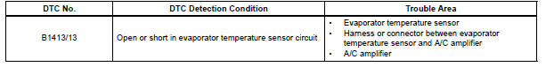
WIRING DIAGRAM 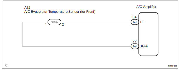
INSPECTION PROCEDURE
1 READ VALUE OF INTELLIGENT TESTER
(a) Connect the intelligent tester to the DLC3.
(b) Turn the ignition switch to the ON position and turn the intelligent tester main switch on.
(c) Select the item below in the DATA LIST, and read the display on the intelligent tester.
DATA LIST / AIR CONDITIONER: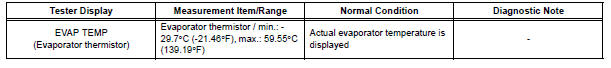
OK: The display is as specified in the normal condition column.
Result 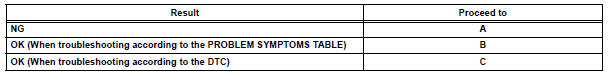

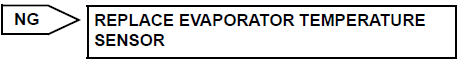
2 INSPECT EVAPORATOR TEMPERATURE SENSOR
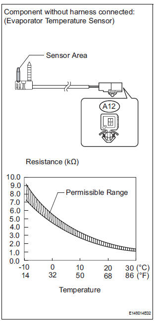
(a) Disconnect the connector from the evaporator temperature sensor.
(b) Measure the resistance according to the value(s) in the table below.
Standard resistance 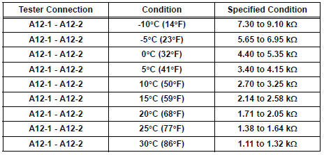
NOTICE:
- Even slightly touching the sensor may change the resistance value. Be sure to hold the connector of the sensor.
- When measuring, the sensor temperature must be the same as the evaporator temperature.
HINT: As the temperature increases, the resistance decreases (see the graph).

3 CHECK HARNESS AND CONNECTOR (EVAPORATOR TEMPERATURE SENSOR - A/C AMPLIFIER)
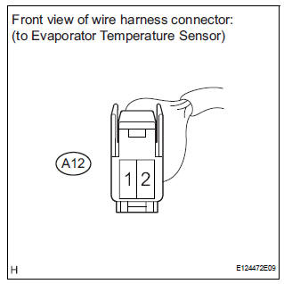
(a) Disconnect the evaporator temperature sensor connector.
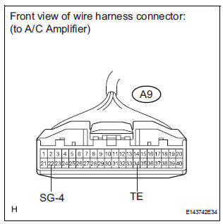
(b) Disconnect the A/C amplifier connector.
(c) Measure the resistance according to the value(s) in the table below.
Standard resistance 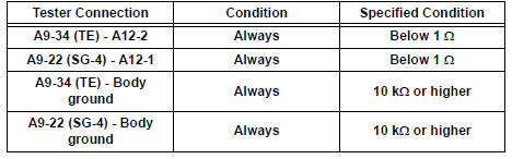

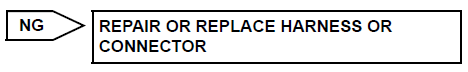
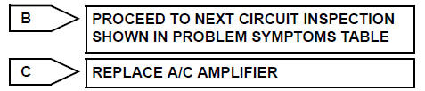
REPLACE A/C AMPLIFIER
 Ambient temperature sensor circuit
DTC B1412/12 Ambient Temperature Sensor Circuit
DESCRIPTION
The ambient temperature sensor is installed in front of the condenser to
detect the ambient temperature
which is used to control the ai ...
 Rear evaporator temperature sensor circuit
DESCRIPTION
The rear evaporator temperature sensor is installed on the rear evaporator.
It detects the rear evaporator
temperature. The sensor sends a signal to the A/C amplifier. The resistance o ...
Other materials:
Removal
1. DRAIN BRAKE FLUID
NOTICE:
Wash brake fluid off immediately if it adheres to any
painted surface.
2. DISCONNECT BATTERY NEGATIVE TERMINAL
3. REMOVE AIR CLEANER ASSEMBLY WITH HOSE
4. REMOVE BRAKE ACTUATOR WITH BRACKET
(a) Release the latch of the brake actuator connector to
disconnect the c ...
DSP Error
DTC 63-78 DSP Error
DESCRIPTION
DTC No.
DTC Detection Condition
Trouble Area
63-78
An error occurs during the decode process (MP3 /
WMA).
-
INSPECTION PROCEDURE
HINT:
After the inspection completed, clear the DTCs.
NOTICE:
This ...
Preparation 2gr-fe engine mechanical
SST
RECOMMENDED TOOLS
EQUIPMENT
HINT:
Torx is registered trademark of Textron Inc.
SSM
...
