Toyota Sienna Service Manual: Front Airbag Sensor LH Circuit Malfunction
DTC B1149/37 Front Airbag Sensor LH Circuit Malfunction
DESCRIPTION
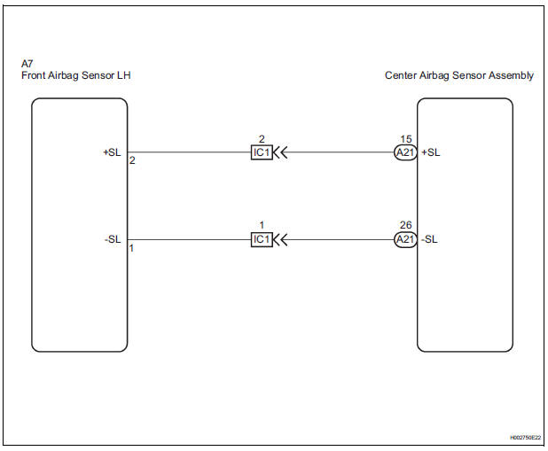
The front airbag sensor LH circuit consists of the center airbag sensor assembly and front airbag sensor LH.
If the center airbag sensor assembly receives signals from the front airbag sensor LH, it judges whether or not the SRS should be activated.
DTC B1149/37 is recorded when a malfunction is detected in the front airbag sensor LH circuit
|
DTC No. |
DTC Detecting Condition |
Trouble Area |
|
B1149/37 |
|
|
WIRING DIAGRAM
INSPECTION PROCEDURE
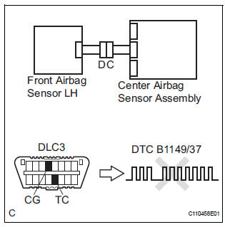
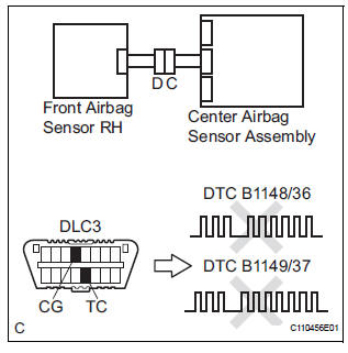
1 CHECK DTC
- Turn the ignition switch to the ON position, and wait for at least 60 seconds.
- Clear the DTCs stored in memory (5).
- Turn the ignition switch to the LOCK position.
- Turn the ignition switch to the ON position, and wait for at least 60 seconds.
- Check the DTCs (5).
OK: DTC B1149/37 is not output. HINT: Codes other than DTC B1149/37 may be output at this time, but they are not related to this check.
 Go to step 2

USE SIMULATION METHOD TO CHECK
2 CHECK CONNECTION OF CONNECTORS
- Turn the ignition switch to the LOCK position.
- Disconnect the negative (-) terminal cable from the battery, and wait for at least 90 seconds.
- Check that the connectors are properly connected to the center airbag sensor assembly and the front airbag sensor LH.
OK: The connectors are connected
 CONNECT CONNECTORS

3 CHECK FRONT AIRBAG SENSOR LH CIRCUIT (OPEN)
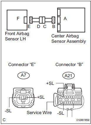
- Disconnect the connectors from the center airbag sensor assembly and the front airbag sensor LH.
- Using a service wire, connect A21-15 (+SL) and A21-26
(-SL) of connector "B".
NOTICE: Do not forcibly insert a service wire into the terminals of the connector when connecting.
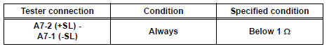
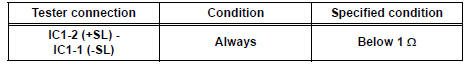
- Measure the resistance according to the value(s) in the table below.
Standard resistance
 Go to step 5

4 CHECK FRONT AIRBAG SENSOR LH
- Disconnect the service wire from connector "B".
- Connect the connector to the center airbag sensor assembly.
- Interchange the front airbag sensor RH with LH and connect the connectors to them.
- Connect the negative (-) terminal cable to the battery, and wait for at least 2 seconds.
- Turn the ignition switch to the ON position, and wait for at least 60 seconds.
- Clear the DTCs stored in memory (5).
- Turn the ignition switch to the LOCK position.
- Turn the ignition switch to the ON position, and wait for at least 60 seconds.
- Check the DTCs (5).
Result
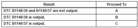
HINT: Codes other than DTC B1148/36 and B1149/37 may be output at this time, but they are not related to this check
 REPLACE FRONT AIRBAG SENSOR
LH
REPLACE FRONT AIRBAG SENSOR
LH
 REPLACE CENTER AIRBAG SENSOR
ASSEMBLY
REPLACE CENTER AIRBAG SENSOR
ASSEMBLY

USE SIMULATION METHOD TO CHECK
5 CHECK INSTRUMENT PANEL WIRE (OPEN)
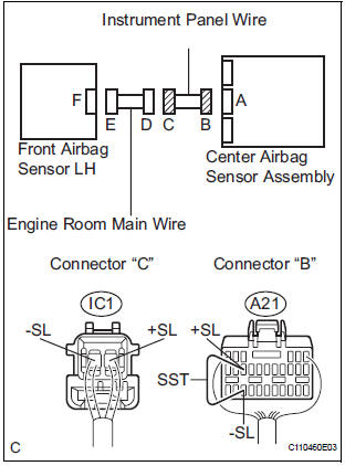
- Disconnect the instrument panel wire connector from the
engine room main wire.
HINT: The service wire has already been inserted into connector "B".
- Measure the resistance according to the value(s) in the table below.
Standard resistance
 REPAIR OR REPLACE INSTRUMENT
PANEL
WIRE
REPAIR OR REPLACE INSTRUMENT
PANEL
WIRE

REPAIR OR REPLACE ENGINE ROOM MAIN WIRE
 Front Airbag Sensor RH Circuit Malfunction
DTC B1148/36 Front Airbag Sensor RH Circuit Malfunction
DESCRIPTION
The front airbag sensor RH circuit consists of the center airbag sensor
assembly and front airbag sensor
RH. If the center airb ...
 Occupant Classification System Malfunction
DTC B1150/23 Occupant Classification System Malfunction
DESCRIPTION
The occupant classification system circuit consists of the center airbag
sensor assembly and the occupant
classification ECU.
...
Other materials:
2Gr-fe engine mechanical
SERVICE DATA
TORQUE SPECIFICATIONS
2GR-FE FUEL
SERVICE DATA
TORQUE SPECIFICATIONS
2GR-FE EMISSION CONTROL
SERVICE DATA
TORQUE SPECIFICATIONS
2GR-FE INTAKE
SERVICE DATA
TORQUE SPECIFICATIONS
2GR-FE EXHAUST
SERVICE DATA
TORQUE SPECIFICAT ...
Terminals of ECU
1. CHECK DISTANCE CONTROL ECU
Reference: waveform 1
HINT:
Terminal: LRDD - SGND
Gauge set: 2 V/DIV., 10 ms./DIV.
Condition: ignition switch in the ON position
Reference: waveform 2
HINT:
Terminal: LRRD - SGND
Gauge set: 2 V/ ...
Warning light and indicator light bulb check
(a) Check the warning lights.
(1) Release parking brake pedal.
(2) When the ignition switch is turned to the ON
position, check that the ABS warning light,
BRAKE warning light, VSC warning light, TRAC
OFF indicator light (2WD) and SLIP indicator
light stay on for approx. 3 seconds.
HI ...
