Toyota Sienna Service Manual: Fuel tank
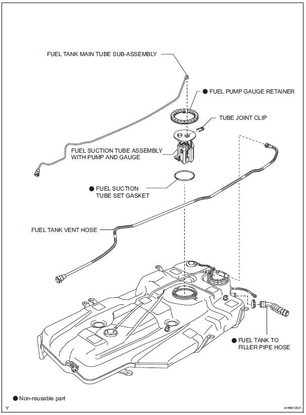
Components
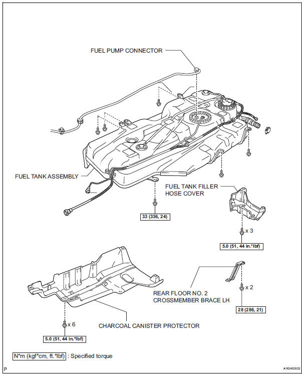
REMOVAL
1. DISCHARGE FUEL SYSTEM PRESSURE (See page FU-1)
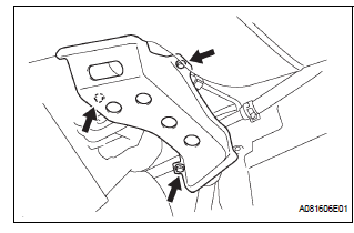
2. REMOVE CHARCOAL CANISTER PROTECTOR (See page FU-30) 3. REMOVE REAR FLOOR NO. 2 CROSSMEMBER BRACE LH
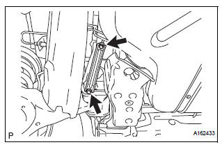
(a) Remove the 2 bolts and the rear floor No. 2 crossmember brace LH.
4. REMOVE FUEL TANK FILLER HOSE COVER
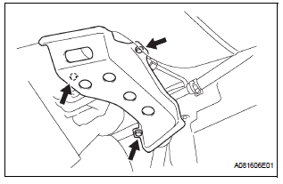
(a) Remove the 3 bolts and the fuel tank filler hose cover.
5. REMOVE FUEL TANK ASSEMBLY
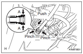
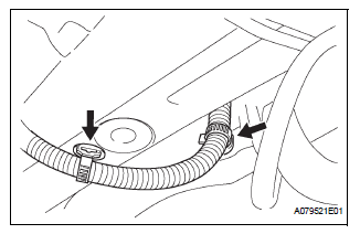
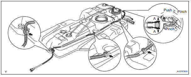
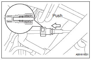
(a) Disconnect the fuel tank vent hose.
(1) Deeply push the connector to release the locking tab.
(2) Pinch portion A.
(3) Pull out the connector.
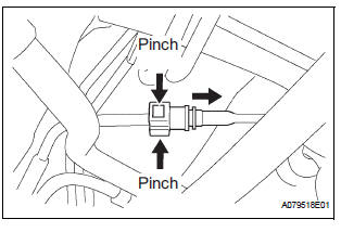
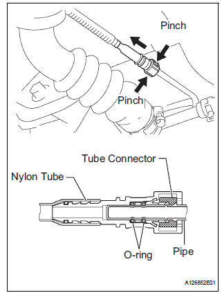
(b) Disconnect the fuel tank main tube sub-assembly.
(1) Pinch the tube connector and then pull out the fuel tank main tube sub-assembly.
NOTICE:
|
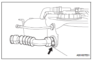
(c) Disconnect the fuel tank to filler pipe hose.
(1) Loosen the hose clamp bolt and disconnect the fuel tank to filler pipe hose.
(d) Disconnect the fuel tube.
(1) Pinch the tube connector and then pull out the fuel tank main tube sub-assembly.
NOTICE:
|
(e) Remove the 2 wire harness clamps.
(f) Set up a transmission jack under the fuel tank assembly.
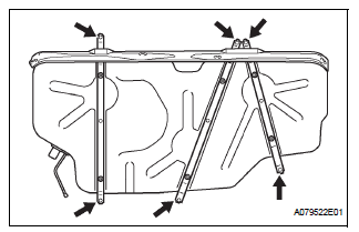
(g) Remove the 6 set bolts of the 3 fuel tank bands.
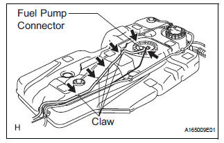
(h) While operating the transmission jack, unfasten the 4 claws for the wire harness and disconnect the fuel pump connector, then remove the fuel tank and the 3 fuel tank bands from the vehicle.
6. REMOVE FUEL TANK MAIN TUBE SUB-ASSEMBLY (See page FU-30)
7. REMOVE FUEL SUCTION TUBE ASSEMBLY WITH PUMP AND GAUGE (See page FU-31)
8. DRAIN FUEL
9. REMOVE FUEL TANK TO FILLER PIPE HOSE
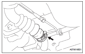
(a) Loosen the hose clamp bolt and remove the fuel tank to filler pipe hose from the fuel tank.
10. REMOVE FUEL TANK VENT HOSE
(a) Remove the hose of the fuel tank vent hose from the 3 hose clamps.
(b) Remove the fuel tank vent hose.
(1) Deeply push the connector to release the locking tab.
(2) Pinch portion A.
(3) Pull out the connector.
Installation
1. CONNECT FUEL TANK VENT HOSE
2. INSTALL FUEL TANK TO FILLER PIPE HOSE
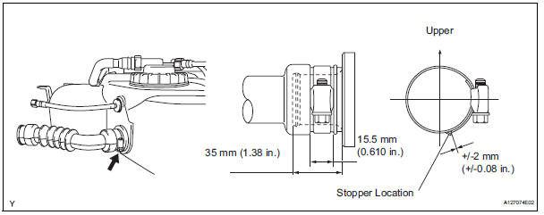
a) Install a new fuel tank to filler pipe hose as shown in the illustration.
3. INSTALL FUEL SUCTION TUBE ASSEMBLY WITH PUMP AND GAUGE (See page FU-34) 4. INSTALL FUEL TANK MAIN TUBE SUB-ASSEMBLY (See page FU-35) 5. INSTALL FUEL TANK ASSEMBLY
(a) Set up the fuel tank assembly to the transmission jack.
(b) While operating the transmission jack, fasten the 4 claws for the wire harness and connect the fuel pump connector, then install the fuel tank and the 3 fuel tank bands to the vehicle.
(c) Tighten the 6 set bolts of the 3 fuel tank bands.
Torque: 33 N*m (336 kgf*cm, 24 ft.*lbf) (d) Install the 2 wire harness clamps.
(e) Connect the fuel tube.

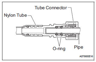
(1) Push in the fuel tube connector to the pipe until fuel tube connector makes "click" sound.
NOTICE:
|
(f) Connect the fuel tank to filler pipe hose as shown in the illustration.
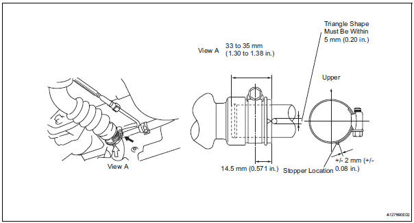
(g) Connect the fuel tank main tube.
(1) Push in the fuel tube connector to the pipe until fuel tube connector makes "click" sound.
NOTICE:
|
(h) Connect the fuel tank vent hose.
6. ADD FUEL
7. INSPECT FOR FUEL LEAK (See page FU-7)
8. INSTALL FUEL TANK FILLER HOSE COVER
(a) Install the 3 bolts and the fuel tank filler hose cover.
Torque: 5.0 N*m (51 kgf*cm, 44 in.*lbf)
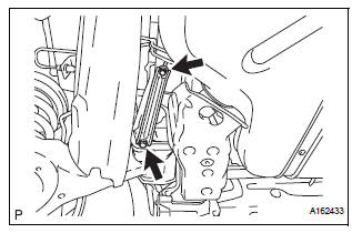
9. INSTALL REAR FLOOR NO. 2 CROSSMEMBER BRACE LH
(a) Install the rear floor No. 2 crossmember brace LH with 2 bolts.
Torque: 28 N*m (286 kgf*cm, 21 ft.*lbf)
10. INSTALL CHARCOAL CANISTER PROTECTOR (See page FU-36)
 Fuel pump resistor
Components
REMOVAL
1. REMOVE FUEL PUMP RESISTOR
(a) Disconnect the connector.
(b) Remove the nut and fuel pump resistor.
INSPECTION
1. INSPECT FUEL PUMP RESISTOR
(a) Inspect fuel ...

Other materials:
Identification information
VEHICLE IDENTIFICATION AND SERIAL NUMBERS
1. VEHICLE IDENTIFICATION NUMBER
(a) The vehicle identification number is stamped on the
vehicle identification number plate and the
certification label, as shown in the illustration.
A:
Vehicle Identification Number Plate
B:
...
Correct use of the seat belts
Make sure that all occupants are wearing their seat belts before driving
the vehicle. Use a child restraint system appropriate for the child until the child
becomes large enough to properly wear the vehicle’s seat belt.
Adjusting the mirrors
Make sure that you can see backward clearly by adjus ...
Definition of terms
Term
Definition
Monitor description
Description of what the ecm monitors and how it detects malfunctions
(monitoring purpose and its details).
Related dtcs
Diagnostic codeV
Typical enabling condition
Preconditions that allow the ecm to detect malfunc ...
