Toyota Sienna Service Manual: Engine Coolant Temperature Circuit Range / Performance Problem

DESCRIPTION
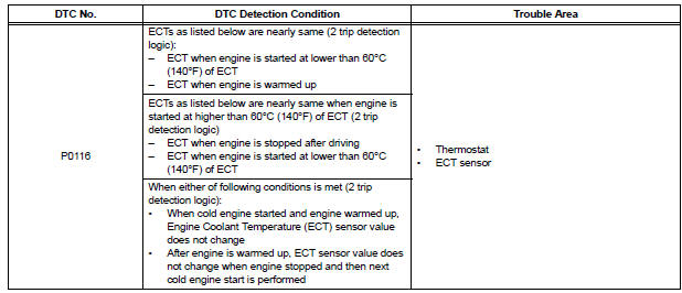
Refer to DTC P0115 (See page ES-133).
MONITOR DESCRIPTION
The ECT sensor is used to monitor the ECT. The ECT sensor has a built-in thermistor with a resistance that varies according to the temperature of the engine coolant. When the ECT becomes low, the resistance of the thermistor increases. When the temperature becomes high, the resistance drops. These variations in the resistance are reflected in the voltage output from the ECT sensor.
The ECM monitors the sensor voltage and uses this value to calculate the ECT. If the sensor voltage output deviates from the normal operating range, the ECM interprets this deviation as a malfunction in the ECT sensor and sets the DTC.
Examples:
- Upon starting the engine, the ECT is between 35ÂḞC and 60ÂḞC (95ÂḞF and 140ÂḞF). If the ECT remains within 3ÂḞC (5.4ÂḞF) of the stating temperature after driving for 250 seconds, the DTC is set (2 trip detection logic).
- Upon starting the engine, the ECT is over 60ÂḞC (140ÂḞF). If the ECT remains within 1ÂḞC (1.8ÂḞF) of the starting temperature after driving for 250 seconds, the DTC is set (6 trip detection logic).
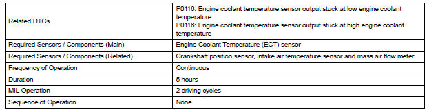
MONITOR STRATEGY
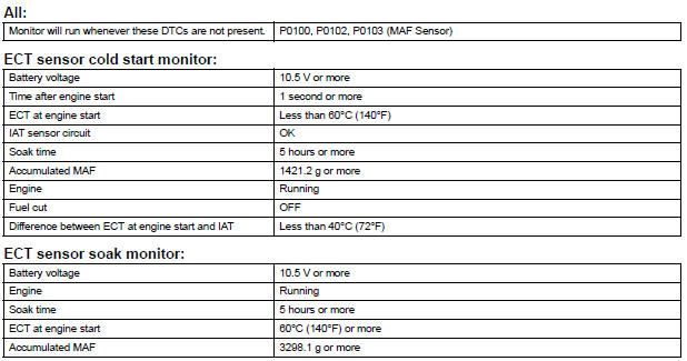
TYPICAL ENABLING CONDITIONS
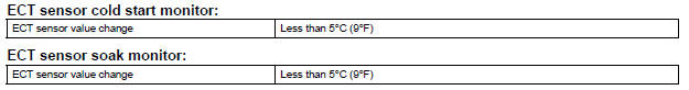
TYPICAL MALFUNCTION THRESHOLDS
COMPONENT OPERATING RANGE

INSPECTION PROCEDURE
HINT:
- If any of DTC P0115, P0117, P0118 or P0125 are set simultaneously with DTC P0116, the ECT sensor may have an open or a short circuit. Troubleshoot those DTCs first.
- Read freeze frame data using the intelligent tester. The ECM records vehicle and driving condition information as freeze frame data the moment a DTC is stored. When troubleshooting, freeze frame data can be helpful in determining whether the vehicle was running or stopped, whether the engine was warmed up or not, whether the air-fuel ratio was lean or rich, as well as other data recorded at the time of a malfunction.
1 CHECK ANY OTHER DTCS OUTPUT (IN ADDITION TO DTC P0166)
(a) Connect the intelligent tester to the DLC3.
(b) Turn the ignition switch to the ON position.
(c) Turn the tester on.
(d) Enter the following menus: DIAGNOSIS / ENHANCED II / DTC INFO / CURRENT CODES.
(e) Read the DTC.
Result 

2 INSPECT THERMOSTAT
(a) Remove the thermostat (See page CO-16).
(b) Check the valve opening temperature of the thermostat.
Standard: 80 to 84ÂḞC (176 to 183ÂḞF)
HINT:
In addition to the above check, confirm that the valve is completely closed when the temperature is below the standard.
(c) Reinstall the thermostat (See page CO-17).


REPLACE ENGINE COOLANT TEMPERATURE SENSOR
 Engine Coolant Temperature Circuit
DESCRIPTION
A thermistor is built into the Engine Coolant Temperature (ECT) sensor, of
which the resistance value
varies according to the ECT.
The structure of the sensor and its connection ...
 Engine Coolant Temperature / Intake Air Temperature Correlation
DESCRIPTION
The ECM calculates the difference between the readings of the coolant
temperature sensor and intake air
temperature sensor. If the difference is greater than 20ÂḞC (68ÂḞF), the ECM ...
Other materials:
Removal
1. REMOVE FRONT FENDER LINER LH
2. REMOVE FRONT FENDER LINER RH
3. REMOVE FRONT BUMPER COVER
4. REMOVE FRONT BUMPER ENERGY ABSORBER
5. REMOVE FRONT BUMPER REINFORCEMENT SUBASSEMBLY
6. REMOVE LASER SENSOR
Disconnect the connector and remove the laser the
sensor.
...
Perform monitor drive pattern
The monitor results and test values can be checked with
the OBD II scan tool or the intelligent tester. The engine
control module (ECM) monitors the emissions-related
components such as the thermostat, catalyst converter
and evaporative emissions (EVAP), and determines
whether they are function ...
Meter panel light control
The brightness of the meter panel lights can be adjusted.
Pressing the button will adjust the
brightness of the meter panel
lights.
The brightness level of the meters
when the surroundings are bright
(day mode) and dark (night mode)
can be adjusted individually. However,
when in day ...
