Toyota Sienna Service Manual: Rear Occupant Classification Sensor RH Circuit Malfunction
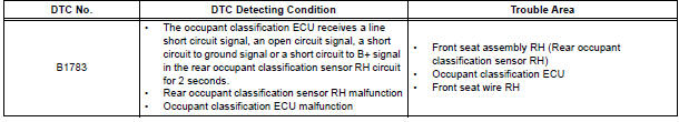
DTC B1783 Rear Occupant Classification Sensor RH Circuit Malfunction
DESCRIPTION
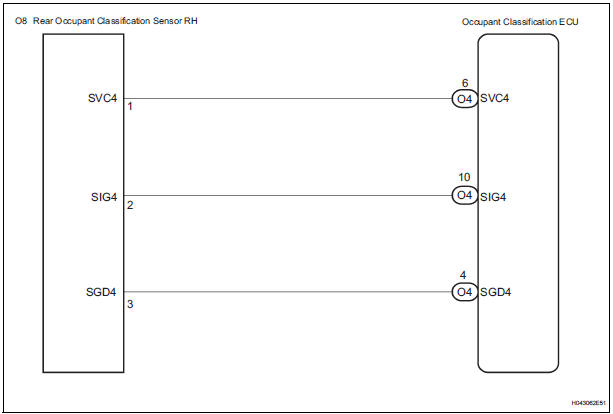
The rear occupant classification sensor RH circuit consists of the occupant classification ECU and the rear occupant classification sensor RH.
DTC B1783 is recorded when a malfunction is detected in the rear occupant classification sensor RH circuit.
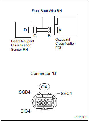
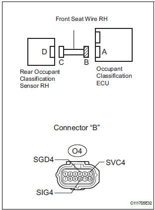
WIRING DIAGRAM
INSPECTION PROCEDURE
HINT:
- If troubleshooting (wire harness inspection) is difficult to perform, remove the front passenger seat installation bolts to see the under surface of the seat cushion.
- In the above case, hold the seat so that it does not fall down. Holding the seat for a long period of time may cause a problem, such as seat rail deformation. Hold the seat only as necessary.
1 CHECK DTC
- Turn the ignition switch to the ON position.
- Clear the DTCs stored in the memory.
HINT: First clear DTCs stored in the occupant classification ECU and then in the center airbag sensor assembly.
- Turn the ignition switch to the LOCK position.
- Turn the ignition switch to the ON position.
- Check the DTCs.
OK: DTC B1783 is not output.
HINT: Codes other than DTC B1783 may be output at this time, but they are not related to this check.
2 CHECK CONNECTION OF CONNECTORS
- Turn the ignition switch to the LOCK position.
- Disconnect the negative (-) terminal cable from the battery, and wait for at least 90 seconds.
- Check that the connectors are properly connected to the occupant classification ECU and the rear occupant classification sensor RH.
OK: The connectors are properly connected.
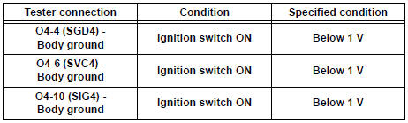
3 CHECK FRONT SEAT WIRE RH (SHORT TO B+)
- Disconnect the connectors from the occupant classification ECU and the rear occupant classification sensor RH.
- Connect the negative (-) terminal cable to the battery.
- Turn the ignition switch to the ON position.
- Measure the voltage according to the value(s) in the table below.
Standard voltage
4 CHECK FRONT SEAT WIRE RH (OPEN)
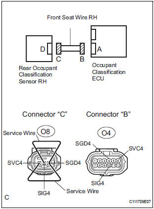
- Turn the ignition switch to the LOCK position.
- Disconnect the negative (-) terminal cable from the battery, and wait for at least 90 seconds.
- Using a service wire, connect O8-1 (SVC4) and O8-3
(SGD4), and connect O8-2 (SIG4) and O8-3 (SGD4) of
connector "C".
NOTICE: Do not forcibly insert a service wire into the terminals of the connector when connecting.
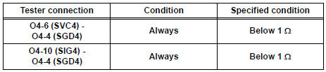
- Measure the resistance according to the value(s) in the table below.
Standard resistance
5 CHECK FRONT SEAT WIRE RH (SHORT)
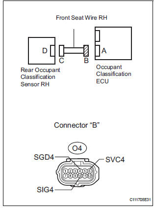
- Disconnect the service wire from connector "C".
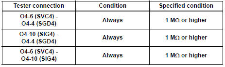
- Measure the resistance according to the value(s) in the table below.
Standard resistance
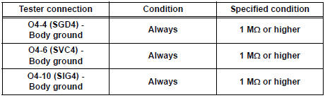
6 CHECK FRONT SEAT WIRE RH (SHORT TO GROUND)
- Measure the resistance according to the value(s) in the table below.
Standard resistance
7 CHECK DTC
- Connect the connectors to the occupant classification ECU and the rear occupant classification sensor RH.
- Connect the negative (-) terminal cable to the battery.
- Turn the ignition switch to the ON position.
- Clear the DTCs stored in the memory.
HINT: First clear DTCs stored in the occupant classification ECU and then in the center airbag sensor assembly.
- Turn the ignition switch to the LOCK position.
- Turn the ignition switch to the ON position.
- Check the DTCs.
OK: DTC B1783 is not output.
HINT: Codes other than DTC B1783 may be output at this time, but they are not related to this check.
8 REPLACE OCCUPANT CLASSIFICATION ECU
- Turn the ignition switch to the LOCK position.
- Disconnect the negative (-) terminal cable from the battery, and wait for at least 90 seconds.
- Replace the occupant classification ECU.
HINT: Perform the inspection using parts from a normal vehicle if possible.
9 PERFORM ZERO POINT CALIBRATION
- Connect the negative (-) terminal cable to the battery.
- Connect the intelligent tester to the DLC3.
- Turn the ignition switch to the ON position.
- Using the intelligent tester, perform "Zero point calibration".
OK: "COMPLETED" is displayed.
10 PERFORM SENSITIVITY CHECK
- Using the intelligent tester, perform "Sensitivity check".
Standard value: 27 to 33 kg (59.52 to 72.75 lb)
11 CHECK DTC
- Connect the negative (-) terminal cable to the battery.
- Turn the ignition switch to the ON position.
- Clear the DTCs stored in the memory.
HINT: First clear DTCs stored in the occupant classification ECU and then in the center airbag sensor assembly.
- Turn the ignition switch to the LOCK position.
- Turn the ignition switch to the ON position.
- Check the DTCs.
OK: DTC B1783 is not output.
HINT: Codes other than DTC B1783 may be output at this time, but they are not related to this check.
12 REPLACE FRONT SEAT ASSEMBLY RH
- Turn the ignition switch to the LOCK position.
- Disconnect the negative (-) terminal cable from the battery, and wait for at least 90 seconds.
- Replace the front seat assembly RH ( for flat type, SE-48 for manual seat, SE-58 for power seat).
13 PERFORM ZERO POINT CALIBRATION
- Connect the negative (-) terminal cable to the battery.
- Connect the intelligent tester to the DLC3.
- Turn the ignition switch to the ON position.
- Using the intelligent tester, perform "Zero point calibration"
OK: "COMPLETED" is displayed.
14 PERFORM SENSITIVITY CHECK
- Using the intelligent tester, perform "Sensitivity check".
Standard value: 27 to 33 kg (59.52 to 72.75 lb)
END
 Rear Occupant Classification Sensor LH Circuit
Malfunction
Rear Occupant Classification Sensor LH Circuit
Malfunction
DTC B1782 Rear Occupant Classification Sensor LH Circuit
Malfunction
DESCRIPTION
The rear occupant classification sensor LH circuit consists of the occupant
classification ECU and the rear
occup ...
 Front Occupant Classification Sensor LH Collision
Detection
Front Occupant Classification Sensor LH Collision
Detection
DTC B1785 Front Occupant Classification Sensor LH Collision
Detection
DESCRIPTION
DTC B1785 is output when the occupant classification ECU receives a collision
detection signal sent by
the front ...
Other materials:
Touch Panel Switch does not Function
INSPECTION PROCEDURE
1 CHECK TOUCH PANEL
Check for foreign matter on the display.
OK:
The display is clean
2 CHECK TOUCH SWITCH (DISPLAY CHECK MODE)
Enter the "Display Check" mode (Touch Switch Check).
Touch the display in the area where the switch
malfunction o ...
How to proceed with
troubleshooting
HINT:
Troubleshoot in accordance with the procedures on the
following pages
1 VEHICLE BROUGHT TO WORKSHOP
2 CUSTOMER PROBLEM ANALYSIS CHECK AND SYMPTOM CHECK
3 INSPECT COMMUNICATION FUNCTION OF LARGE-SCALE MULTIPLEX
COMMUNICATION SYSTEM (BEAN)
Use the intelligent tester to check for normal ...
Installation
1. INSTALL REAR COIL SPRING INSULATOR UPPER LH
(a) Install the insulator upper LH to the coil spring rear
LH.
2. INSTALL COIL SPRING REAR LH
(a) Apply a shop rug to the rear axle beam assembly.
(b) Install the coil spring rear LH to the rear axle beam
assembly.
HINT:
Fit the lowe ...
