Toyota Sienna Service Manual: Rear wiper rubber
COMPONENTS
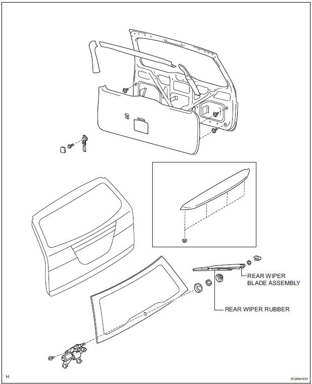
REMOVAL
1. REMOVE REAR WIPER BLADE ASSEMBLY
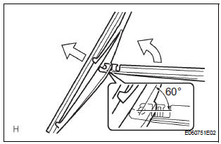
- Remove the rear wiper arm head cap from the rear wiper arm.
- Raise the rear wiper blade to the position as shown
in the illustration where the meshing of the claw is
disengaged with the click sound.
NOTICE: Be careful not to break the claw.
- Pull the rear wiper blade straight from the wiper arm toward the left side of the vehicle.
NOTICE: Do not fold the rear wiper arm with the rear wiper blade being removed from it.
2. REMOVE REAR WIPER RUBBER
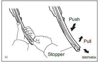
- Pull the end of the rubber protruded from the blade stopper as shown in the illustration.
NOTICE: Do not pull out the wiper rubber forcibly.
Otherwise, the backing plates are deformed or blade claw is damaged. HINT: Pushing the position close to the middle of the blade raises the rubber, making easier to pull the rubber out.
INSTALLATION
1. INSTALL REAR WIPER RUBBER
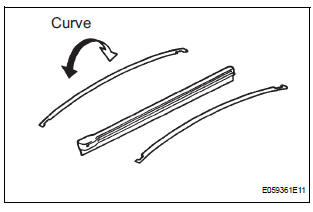
- Install the 2 wiper rubber backing plates to the rear wiper rubber.
NOTICE: Be sure to install the wiper rubber backing plates in the right direction.
 Rear wiper motor and bracket
COMPONENTS
REMOVAL
1. REMOVE REAR WIPER ARM
Remove the rear wiper arm head cap from the rear
wiper arm.
Remove the nut and the rear wiper arm.
2. REMOVE BACK DOOR GARN ...
 Wiper switch
COMPONENTS
REMOVAL
1. REMOVE STEERING COLUMN COVER
2. REMOVE WINDSHIELD WIPER SWITCH ASSEMBLY
Disconnect the connector.
Using a screwdriver, disengage the claw and pull
...
Other materials:
Chassis
GENERAL MAINTENANCE
1. INSPECT STEERING LINKAGE
(a) Check the steering linkage for looseness or
damage.
Check that:
Tie rod ends do not have excessive play.
Dust seals and boots are not damaged.
Boot clamps are not loose.
(b) Inspect the dust cover for damage.
2. INSPECT STEERING G ...
Taillight Relay Circuit
DESCRIPTION
The Multiplex network body ECU controls TAIL relay when signal is received
from headlight dimmer
switch assembly.
WIRING DIAGRAM
INSPECTION PROCEDURE
1 PERFORM ACTIVE TEST BY INTELLIGENT TESTER
Connect the intelligent tester to DLC3.
Turn the ignition switch ON and ...
Setting the vehicle speed
Press the “ON-OFF” button to
activate the cruise control.
Cruise control indicator will come
on*1 or will be displayed on the
multi-information display*2.
Press the button again to deactivate
the cruise control.
Accelerate or decelerate the
vehicle to the desired s ...
