Toyota Sienna Service Manual: High mounted stop light assembly
COMPONENTS
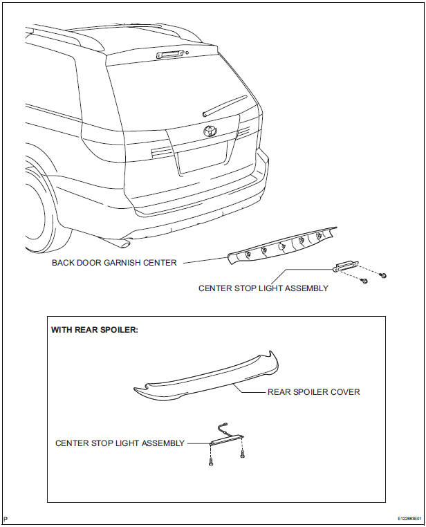
REMOVAL
1. REMOVE BACK DOOR GARNISH CENTER (w/ Rear Spoiler)
2. REMOVE REAR SPOILER COVER (w/ Rear Spoiler)
3. REMOVE CENTER STOP LIGHT ASSEMBLY
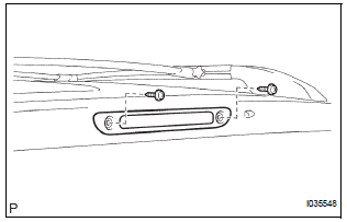
- w/o Rear spoiler:
- Disconnect the connector and remove the 2 screws and the center stop light assembly.
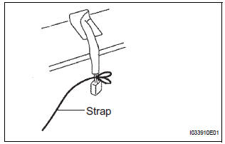
- w/ Rear spoiler:
- Install the strap on the connector of the center stop light assembly.
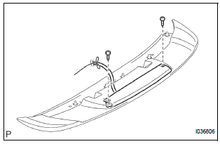
- w/ Rear spoiler:
- Remove the 2 screws.
- w/ Rear spoiler:
- Pass the connector through the inside of the rear spoiler sub-assembly, and remove the center stop light assembly.
HINT: Leave the strap inside the rear spoiler subassembly.
INSTALLATION
1. INSTALL CENTER STOP LIGHT ASSEMBLY
2. INSTALL REAR SPOILER COVER
3. INSTALL BACK DOOR GARNISH CENTER
 License plate light assembly
COMPONENTS
REMOVAL
1. REMOVE BACK DOOR GARNISH CENTER
2. REMOVE BACK DOOR SIDE GARNISH LH
3. REMOVE BACK DOOR SIDE GARNISH RH
4. REMOVE BACK DOOR STRAP COVER
5. REMOVE BACK DOOR PULL STR ...
 Personal light assembly
ON-VEHICLE INSPECTION
1. ROOF CONSOLE BOX ASSEMBLY
Inspect map light assembly resistance.
Check the resistance between the terminals at
each switch position as shown in th ...
Other materials:
List of storage features
Auxiliary boxes
Cup holders
Door pockets
Bottle holders
Glove boxes
Console box (if equipped)
WARNING
Do not leave glasses, lighters or spray cans in the storage
spaces, as this
may cause the following when cabin temperature becomes high:
Glas ...
“Contact/Call History Settings” screen
Display the “Phone/Message Settings” screen.
Select “Contact/Call History Settings”.
Select the desired item to be set.
For PBAP compatible
Bluetooth® phones, select to
set “Automatic Transfer” on/
off. When set to on, the
phone’s contact data and history
a ...
Before refueling the vehicle
Close all the doors and windows, and turn the engine switch to the
“LOCK” position (vehicles without a smart key system) or off (vehicles
with a smart key system).
Confirm the type of fuel.
Fuel type
Fuel tank opening for unleaded gasoline
To help prevent incorrect fueling, your ve ...
