Toyota Sienna Service Manual: How to proceed with troubleshooting
HINT:
- Use this procedure to troubleshoot the engine immobiliser system.
- The intelligent tester should be used in steps 4, 5 and 7.
1 VEHICLE BROUGHT TO WORKSHOP
2 CUSTOMER PROBLEM ANALYSIS CHECK AND SYMPTOM CHECK
3 CRANK ENGINE FOR MORE THAN 10 SECONDS
4 CHECK FOR DTC
- Check for DTCs and note any codes that are output.
- Delete the DTC.
- Recheck for DTCs. Try to prompt the DTC (SFI system and engine immobiliser system) by simulating the original activity that the DTC suggested.
- If the DTC does not reoccur, proceed to A.
- If the DTC (SFI system) reoccurs, proceed to B.
- If the DTC (engine immobiliser system) reoccurs, proceed to C.
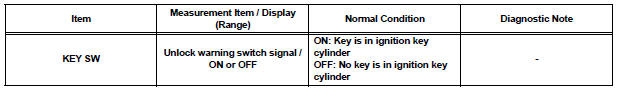
5 READ VALUE OF INTELLIGENT TESTER ((IMMOBILISER ECU (TRANSPONDER KEY ECU ASSEMBLY) (SWITCH CONDITION))
- Connect the intelligent tester to the DLC3.
- Turn the ignition switch ON and push the intelligent tester main switch ON.
- Select the item KEY SW in the DATA LIST and read its value displayed on the intelligent tester.
Transponder key ECU
6 PROBLEM SYMPTOMS TABLE
- If the fault is not listed on the problem symptoms table, proceed to A.
- If the fault is listed on the problem symptoms table, proceed to B
7 OVERALL ANALYSIS AND TROUBLESHOOTING
- Inspection with the intelligent tester (ECU DATA MONITOR).
- Inspection with the intelligent tester (ACTIVE TEST).
- Terminals of ECU
8 ADJUST, REPAIR OR REPLACE
9 CONFIRMATION TEST
END
 Engine immobiliser system
PARTS LOCATION
SYSTEM DESCRIPTION
The engine immobiliser system has been designed to prevent
the vehicle from being stolen. This system uses a
transponder key ECU that stores the key code of t ...
 Registration
1. DESCRIPTION OF CODE REGISTRATION
HINT:
The key has 2 codes: The key code (immobiliser code)
and the wireless code. Both of these codes need to be
registered. Refer to page for the wireless code ...
Other materials:
Power back door touch sensor
INSPECTION
1. INSPECT POWER BACK DOOR TOUCH SENSOR LH
Check the resistance of the sensor.
Resistance
If the result is not as specified, replace the sensor.
2. INSPECT POWER BACK DOOR TOUCH SENSOR RH
Check the resistance of the sensor.
Resistance
If the result is not as ...
Auxiliary boxes
Type A
Push the lid.
Type B
Push down the knob.
Type C (if equipped)
Type D
Type E (if equipped)
Type F
Lift the lid.
Type G (if equipped)
Removing the second center seat.
Type H (if equipped)
Type I (if equip ...
Shift Solenoid "E" Performance (Shift Solenoid
Valve SR)
SYSTEM DESCRIPTION
The ECM uses signals from the vehicle speed sensor to detect the actual gear
position (1st, 2nd, 3rd, 4th
or 5th gear).
Then the ECM compares the actual gear with the shift schedule in the ECM memory
to detect mechanical
problems of the shift solenoid valves, valve b ...
