Toyota Sienna Service Manual: Master Cylinder Pressure Sensor Malfunction
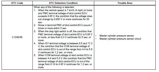
DTC C1246/46 Master Cylinder Pressure Sensor Malfunction
DESCRIPTION
Master cylinder pressure sensor is connected to the skid control ECU in the actuator.
INSPECTION PROCEDURE
1 READ VALUE ON INTELLIGENT TESTER (MASTER CYLINDER PRESSURE SENSOR)
(a) Connect the intelligent tester to the DLC3.
(b) Start the engine.
(c) Select the DATA LIST mode on the intelligent tester.
ABS / VSC: 
(d) Check that the brake fluid pressure value of the master cylinder pressure sensor indicated on the intelligent tester, changes when the brake pedal is depressed.
OK: Brake fluid pressure value should change.
NOTICE: When replacing the brake actuator assembly, perform zero point calibration (See page BC-70).
REPLACE BRAKE ACTUATOR ASSEMBLY
2 INSPECT SKID CONTROL ECU (STP1 TERMINAL)
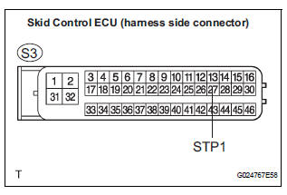
(a) Disconnect the skid control ECU connector.
(b) Measure the voltage according to the value(s) in the table below
Standard voltage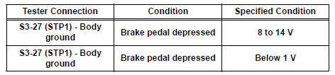
NOTICE: When replacing the brake actuator assembly, perform zero point calibration (See page BC-70).
REPLACE BRAKE ACTUATOR ASSEMBLY
 Low Battery Positive Voltage
DTC C1241/41 Low Battery Positive Voltage
DESCRIPTION
WIRING DIAGRAM
INSPECTION PROCEDURE
1 INSPECT ECU-IG FUSE
(a) Remove the ECU-IG fuse from the driver side J/B.
(b) Check continu ...
 Open in Stop Light Switch Circuit
DTC C1249/49 Open in Stop Light Switch Circuit
DESCRIPTION
WIRING DIAGRAM
INSPECTION PROCEDURE
1 CHECK STOP LIGHT SWITCH OPERATION
(a) Check that the stop light comes on when the brak ...
Other materials:
Disassembly
1. REMOVE FRONT SEAT SIDE TABLE LEG COVER (w/
Table)
Using a screwdriver, disengage the claws and
remove the seat side table leg cover.
HINT:
Tape the screwdriver tip before use.
2. REMOVE FRONT SEAT SIDE TABLE (w/ Table)
Remove the 4 nuts and seat side table.
Rem ...
Open in Front Pretensioner Squib LH Circuit
DTC B0136/74 Open in Front Pretensioner Squib LH Circuit
DESCRIPTION
The front pretensioner squib LH circuit consists of the center airbag sensor
assembly and the front seat
outer belt assembly LH.
This circuit instructs the SRS to deploy when deployment conditions are met.
DTC B0136/74 i ...
Initialization
1. RESET
When the control motor and clutch is replaced:
The power slide door ECU cannot receive a switch
signal from the control motor and clutch. This may
cause the power slide door system to enter fail-safe
mode and DTC (B2224 (LH) or B2223 (RH)) to set,
and also make the syste ...
